hillma
1 mW
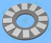
I'm thinking about building a simple axial flux non slotted torus machine (single interior stator with two external rotors) with the idea, if the experiment works, of moving onto a twin stator three rotor design to power my e-bike. I like many others are limited to basic tools but unlimited enthusiasm!
After being motivated by Lebowski's (and others) work on coreless designs I thought a simple torus might be a good way of generating heaps of torque and reducing the amount of reduction required to drive the rear wheel, it will be mid mounted btw.
Basic outline of the machine is:
Rotor
ID = 60mm
OD = 150mm
Thickness = 5mm
Material = Steel
Magnets per rotor = 12 x 30mmx20mmx5mm N50 (total of 24) Magnets arranged NN so that flux is driven circumventionally (is that even a real word?) around the stator to the adjacent magnet on the rotor rather than NS where the flux path passes through the stator to magnet on the opposite rotor.
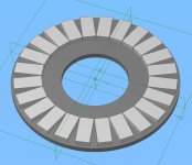
Stator
ID = 84mm
OD = 150mm (ratio of ID/OD = 0.58)
Thickness = 10mm
Material = spiral wound electrical steel
Coils
Total of 36 surface wound coils, 12 per phase
Width = 7mm
Length per turn = 90mm ish (including end turns)
No of turns per coil = 10
Wire = 1.4 mm
I'm hoping to construct this with basic tools and would welcome any comments or observations before I start out. I haven't set myself any parameters for the performance yet as this is mostly a learning exercise at the moment. But if it could eventually manage 1kw and spin at sub 1000rpm efficiently I'll be a happy camper
My main concern at the moment is if the stator is thick enough to not saturate with all the flux being driven though it, (I'm physically limited to 10mm with an eye on the triple rotor design). If this is the case I may need to switch to the NS design where stator thickness is not really an issue but does impact the torque and efficiency.
After being motivated by Lebowski's (and others) work on coreless designs I thought a simple torus might be a good way of generating heaps of torque and reducing the amount of reduction required to drive the rear wheel, it will be mid mounted btw.
Basic outline of the machine is:
Rotor
ID = 60mm
OD = 150mm
Thickness = 5mm
Material = Steel
Magnets per rotor = 12 x 30mmx20mmx5mm N50 (total of 24) Magnets arranged NN so that flux is driven circumventionally (is that even a real word?) around the stator to the adjacent magnet on the rotor rather than NS where the flux path passes through the stator to magnet on the opposite rotor.
Stator
ID = 84mm
OD = 150mm (ratio of ID/OD = 0.58)
Thickness = 10mm
Material = spiral wound electrical steel
Coils
Total of 36 surface wound coils, 12 per phase
Width = 7mm
Length per turn = 90mm ish (including end turns)
No of turns per coil = 10
Wire = 1.4 mm
I'm hoping to construct this with basic tools and would welcome any comments or observations before I start out. I haven't set myself any parameters for the performance yet as this is mostly a learning exercise at the moment. But if it could eventually manage 1kw and spin at sub 1000rpm efficiently I'll be a happy camper
My main concern at the moment is if the stator is thick enough to not saturate with all the flux being driven though it, (I'm physically limited to 10mm with an eye on the triple rotor design). If this is the case I may need to switch to the NS design where stator thickness is not really an issue but does impact the torque and efficiency.