Source for 5V from S12S Controller?

Joined
May 14, 2015
Messages
10
I have an S12S controller with the LCD-3 display. I've decided on going with a 5V USB LED handlebar light with an on/off switch. That means I just need to wire in a female USB connector to get 5V from my controller. I am not using the PAS or speed sensor connectors so those seem like viable 5V sources to me.

Problem is that when I wire those up and try to use them it makes the motor inoperable. Here's what happens:
1. I turn the display on - throttle works fine.
2. I turn the light on - throttle is either unresponsive or goes for a second then cuts out.
3. I turn the display off - nothing works.
4. I turn the display on again - throttle works fine again until I try to use the light.

I'm guessing that the system gets confused when a higher current is pulled by the sensor connector when the light is turned on.

Any ideas? Has anyone been able to use these sensor connectors for 5V power? Other suggestions for getting a 5V power source out of this configuration?

Thanks!
joe
 
I'm pretty sure that none of the 5V sources can handle the current needed to drive a light.

I use a solid state relay, which is switched by the 5V line from my unused throttle input. Here's a picture of my setup. The main battery power goes through a switch, a poly-fuse, the relay, to a DC-DC step-down converter. From there, it's out to my headlight and taillight:

lrJuzu.jpg
 
Yes, it probably has some tiny SMD voltage regulator that is good for maybe 100mA.

Get an external DCDC converter or a light that runs off pack voltage.
 
As the other posts have suggested you need to provide more amps via a DC-DC converter
I recently got this from Aliexpress and it works well with my lights.

http://www.aliexpress.com/item/DC-D...596HVS-LM2596HV-DC-Step-Down/32485142548.html

NB: EDIT I now understand that there does not seem to be any such genuine "LM2596HV" chips.
It might be possible to replace the chip on the PCB with a genuine LM2576HV..... but I have not tested this!!!
My apologies for providing this info - I did it in good faith after watching this video...


https://www.youtube.com/watch?v=JLwJb4MVbls

I am still using this unit but I'm going to check out its temperature when running and then decide if I continue to use it. Alternatively, I may get a DC-DC board based upon a LM2576HV chip - see new post below

NB: Be careful what dc-dc converter you get, most are only rated to around 30VDC (input voltage) .
 
I faced the same dilemma and thought about using the +5V from the PAS wire on my MagicPie 5. I also had one of those generic "Cree T6" lights that connected to 5V USB and thought it would nice to connect it to my main battery pack. After some thoughts, I purchased a 4 LED light with a voltage regulator good from 6-80V and wired it directly to the "light" switch on my throttle controller.

Now, I use my USB light as a backup in my tool bag. I know it's not the answer you were looking for, but it really simplified things and also left me with a functional light switch. ~ $13.
 
ecobully said:
I faced the same dilemma and thought about using the +5V from the PAS wire on my MagicPie 5. I also had one of those generic "Cree T6" lights that connected to 5V USB and thought it would nice to connect it to my main battery pack. After some thoughts, I purchased a 4 LED light with a voltage regulator good from 6-80V and wired it directly to the "light" switch on my throttle controller.

Now, I use my USB light as a backup in my tool bag. I know it's not the answer you were looking for, but it really simplified things and also left me with a functional light switch. ~ $13.

There's no light switch on the S12S controller (which is why I adapted a relay, to turn the lights on when the controller is turned on).
 
Thanks for the input everyone. I've ordered the DC-DC converter that joss recommended and I'll try that route. Does anyone know if there's room inside the S12S controller for the converter? I was in there once before and thought I remember seeing room but I'm not sure.

What is strange here is that the light does work just fine running off of either the PAS or speed sensor connectors. With a 1W light at 5V that means 2A. The circuitry seems to be able to handle it, but maybe not for an extended period of time? Plus that little problem where the motor doesn't work after turning the light on.

Can someone share exactly how the signal line works on those sensor connectors? I understand 5V+ and GND but how does the signal wire work?
 
jhendrickson said:
With a 1W light at 5V that means 2A.

You mean 1A. There was TO-220 and a TO-92 regulators, I didn't measure which was supplying 5V to what.

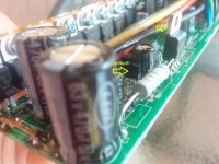
Mine looked pretty tight on space, I wouldn't expect to fit much else in there. But maybe it could be done.

S12S.jpg

With a throttle or motor hall signal it sends an analogue voltage back to the controller depending on how far a magnet is, ranges between about 1 to 4V. Not sure what a PAS signal sends.
 
Gregory said:
jhendrickson said:
With a 1W light at 5V that means 2A.

You mean 1A.
Actually if it's 1W at 5V, it's only 0.2A (200mA). ;)

But realistically it's probably a lot less because it's likely so much extra load on the 5v that it is dragging it's votlage down a lot, maybe more than a volt. (a multimeter would tell us for sure, if the OP will measure it).


jhendrickson said:
I've ordered the DC-DC converter that joss recommended and I'll try that route.
FWIW, it's often possible to use regular wall-wart ac adapters on your battery's DC output, so a regular wall-plug-in type USB power supply might work on the battery to power the light. I've tested several phone chargers that work on my 48v (58.4v full, 50-54v operational typical) pack. I'm also using the original wallwarts taht came with 12v and 15v aquarium lights for my downlighting and kennel/crate ligthing on the SB Cruiser, running off that same battery pack.


What is strange here is that the light does work just fine running off of either the PAS or speed sensor connectors. With a 1W light at 5V that means 2A. The circuitry seems to be able to handle it, but maybe not for an extended period of time? Plus that little problem where the motor doesn't work after turning the light on.
If the motor doesn't work when the light is on, it means the light is drawing so much current that the 5v is sagging so much from the load that the MCU in the controller, or some other necessary circuitry (throttle or PAS hall sensor, etc) cant' get enough voltage to operate (or operate correctly), or the MCU has a protection that detects low-5v line and refuses to operate.
 
Update for the team. I got the DC-DC converter and I think it's going to work. I tried using AC-DC USB power adapters but I got mixed results. Between an Apple, Amazon, and a Blackberry adapter I couldn't get them to work with the 48V battery. However some other adapter I had lying around did work, but while it was supposed to do 5V it was actually putting out 9V both plugged into the wall and off of the 48V battery. I believe that means it is an "unregulated" power supply? I'm guessing the name brand ones have circuitry that make them incompatible with a 48V DC input.

Second note is that while trying to determine just how much voltage I could give my cheap XML-T6 based light http://www.amazon.com/Urparcel-1200...d=1459876027&sr=8-35&keywords=xml+t6+headlamp I over-powered it. At first I thought I burnt out the LED but after opening it up I discovered that a solder connection on the circuit board would melt and disconnect when I got to a certain voltage, it just got too hot. That was around 9V. I'm guessing the LED can take more but the driver board isn't designed to handle it. Looks like it gets the brightest around 6.6V anyway. Also, just a note that the LED in this is definitely not a real CREE. It's a LatticeBright. We'll see how long it lasts.

I'll report back once I crack open the controller to see if I can fit the DC-DC converter board in there and give myself a couple of USB ports for lights and other things.
 
The url link for the light has a USB connector - I wouldn't be putting more than 5vdc in it! Whatever is in the the light (which could be something as simple as a resistor) is not going to be happy with anything else but 5VDC! :wink:
 
joss said:
As the other posts have suggested you need to provide more amps via a DC-DC converter
I recently got this from Aliexpress and it works well with my lights.

http://www.aliexpress.com/item/DC-D...596HVS-LM2596HV-DC-Step-Down/32485142548.html

NB: Be careful what dc-dc converter you get, most are only rated to around 30VDC (input voltage) .

Be careful using the LM2596HV converters as well. The LM2596HV is fake - there's no such model available. It's actually an LM2596. What you can do is replace the fake IC for an LM2576HV.
 
Thanks Flangefrog - you are right I can't find a datasheet for the so called LM2596HV. I posted the link after watching the following video:

https://www.youtube.com/watch?v=JLwJb4MVbls

I may take your advice and change out the board for a genuine LM2576HV based DC-DC converter - purchased from a reputable source! :roll:

I have updated my post above to reflect this information, my most sincere apologies! :?

At the risk of posting more bad information perhaps this is a better bet:

http://www.ebay.com.au/itm/LM2576HV...Power-Supply-Module-Over-LM2596-/180976351390

or....

http://www.amazon.com/SMAKN-LM2576HV-Adjustable-Step-down-1-25-30v/dp/B00ECQOYOQ

I guess there is no guarantee that a chip is a genuine one but at least the number links to a genuine datasheet!!!
 
flangefrog said:
Be careful using the LM2596HV converters as well. The LM2596HV is fake - there's no such model available. It's actually an LM2596. What you can do is replace the fake IC for an LM2576HV.

This is an interesting twist. I did receive an LM2596HV board and tried it following Joss' plans. It burnt out after a few seconds, presumably from the high 54V being pumped into it, although it should have been able to handle it. I also looked into this issue and found the YouTube video myself and just attributed the problem to mine being a cheap knock-off. I didn't find anything that the LM2596HV is entirely fake though.

So I have a five pack of the LM2596HV boards on order from a different supplier and I'll be trying those out when they arrive. I guess if they all fail I'll try out the LM2576HV, but I don't think I'll have to resort to that.

I did put together some wires with an IRF830 mosfet that will connect to the 5V of the PAS connector. That'll give me the auto-on/off from the controller. Now I'm just waiting for the DC-DC converter boards from China. It's slow-going to be cheap, but I have plenty else to work on in the meantime. I lost another spoke this week! But that's another subject.

joe
 
Back
Top