You are using an out of date browser. It may not display this or other websites correctly.
You should upgrade or use an alternative browser.
You should upgrade or use an alternative browser.
StudEbiker's E-Bike-E build- ride vid pg. 7.
- Thread starter StudEbiker
- Start date
recumpence
1 GW
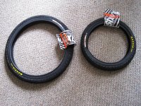
Awesome! I run those on my yellow trike. 
Hmm, I bet I will have my wife's Revive running first. :wink:
Matt
Hmm, I bet I will have my wife's Revive running first. :wink:
Matt
StudEbiker
100 kW
recumpence wrote:Hmm, I bet I will have my wife's Revive running first.
That's a safe bet if there ever was one!
StudEbiker
100 kW
I have been trying to source some of the individual Currie Drive parts and thought that I would keep a log in the thread of where I have found certain parts as cheaply as I could.
The planetary is avaialble @ allelectronics.com for $9.50+$7.00 shipping. http://www.allelectronics.com/make-a-st ... EAR/1.html
PacificAveCycles on Ebay periodically lists some Currie drive parts. I was able to source a bare planetary housing from them for $25+$5 shipping. http://myworld.ebay.com/pacificavecycle ... 4340.l2559
One way roller bearings are available on Ebay and the part #s are: RC-081208 for the 1/2" bearing and HF-1216 for the 12mm bearing.
Matex.com has the splined output shaft that is needed for $10+shipping. The part # is 75-907.
Heavy duty #25 chain is available through electricscooterparts.com (http://www.electricscooterparts.com/chain.html). I have been told that a stock Currie uses 70 links.
As I find more of the parts I will include the source in this post. If anyone knows where to get Currie Drive parts that I haven't listed yet for cheap, please include it in this thread.
StudEbiker
100 kW
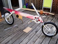
Had a day off and some nice weather so I got to play with the Bike E some today. The cardboard is a mock up of how I plan to mount the motor. There will be another plate on the drive side of the bike with the jackshaft running between them and the freewheel (to the cranks) and the fixed gear (to the rear wheel) will run on the outside of that plate. I am really having fun with this build and am looking forward to getting it going.

StudEbiker
100 kW
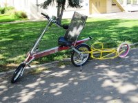
I've still been trying to come up with a good name for this bike and it occurred to me that the Bike E company made models CT, AT, RX, FX, E2, NX and RoadE, but they never made a GT as in Grand Tourer. The GT designation fits right in for what I have in mind for this bike. A nice comfortable cruiser well suited for long trips. So I think it has now become the world's first E-Bike-E GT.  With the trailer the bike is 10'6" long
  It's the Cadillac of CLWB recumbents.
StudEbiker
100 kW
Okay, so my drawing skillz suck. No need to tell me, trust me I know.  Hopefully though this diagram will be enough to explain what I'm doing and maybe get a few questions answered. When I first drew this diagram I was thinking of using a 5/8" jackshaft, but I have since gone to a 1/2", not that it makes much difference for my questions. Here are my questions:
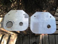
1.) If you look at an earlier picture in this build, you will see the cardboard mock up of how the plate will be mounted on the frame. I am planning on putting three bolts through the frame and the plates to hold the plates in position. I am wondering what thickness metal (and what type of metal) I will need to keep the plates from flexing. The bottom of the plates will be support crosswise by three bolts to add support and reduce flex as well. Can I use aluminum, or is steel the better option? The size of the plates are 10"x7". Is 1/8" enough? Steel or aluminum?
2.) I am using a 1/2" freewheel adapter for the 16t freewheel. The FW adapter has two set screws. One of those is for screwing into the key way to keep it from spinning on the shaft. I am a little unsure of what to do with the other one. Do I put a hole in the shaft a little larger than the setscrew to keep the adapter from moving laterally on the shaft? Does this take the place of a collar lock in this application?
3.) Speaking of collar locks, what about the motor side of the mount. Is the compression of the jackshaft in the bearing enough to keep the shaft from moving, or will I need to put a collar lock on the end?
I guess that's all my questions for now. I'll probably think of some more later though. Thanks.
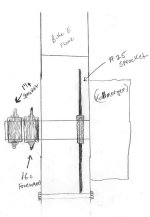

StudEbiker
100 kW
Well, I think I have most of the issues with the jackshaft sorted out now. The outside threaded part is a bottom bracket bearing cup with a 1/2" collar lock put in the hollow part of the bearing cup. I will have a buddy weld the collar lock to the bottom bearing cup then use a track cog to run the chain back to the rear wheel.
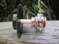
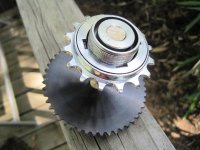


StudEbiker
100 kW
Starting to get the Bike put back together and get the fit right and put some new cables and such on it.
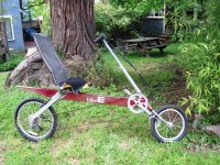
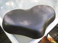
The seat needed covering so I took it to a local upholstery shop and had it covered with the type of material they use for motorcycle seats, very stretchy and durable. No seams needed for a good fit.
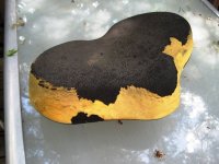

The seat needed covering so I took it to a local upholstery shop and had it covered with the type of material they use for motorcycle seats, very stretchy and durable. No seams needed for a good fit.

Attachments
dontsendbubbamail
10 kW
- Joined
- May 28, 2008
- Messages
- 718
StudEbiker said:Okay, so my drawing skillz suck. No need to tell me, trust me I know.Hopefully though this diagram will be enough to explain what I'm doing and maybe get a few questions answered. When I first drew this diagram I was thinking of using a 5/8" jackshaft, but I have since gone to a 1/2", not that it makes much difference for my questions. Here are my questions:
1.) If you look at an earlier picture in this build, you will see the cardboard mock up of how the plate will be mounted on the frame. I am planning on putting three bolts through the frame and the plates to hold the plates in position. I am wondering what thickness metal (and what type of metal) I will need to keep the plates from flexing. The bottom of the plates will be support crosswise by three bolts to add support and reduce flex as well. Can I use aluminum, or is steel the better option? The size of the plates are 10"x7". Is 1/8" enough? Steel or aluminum?
2.) I am using a 1/2" freewheel adapter for the 16t freewheel. The FW adapter has two set screws. One of those is for screwing into the key way to keep it from spinning on the shaft. I am a little unsure of what to do with the other one. Do I put a hole in the shaft a little larger than the setscrew to keep the adapter from moving laterally on the shaft? Does this take the place of a collar lock in this application?
3.) Speaking of collar locks, what about the motor side of the mount. Is the compression of the jackshaft in the bearing enough to keep the shaft from moving, or will I need to put a collar lock on the end?
I guess that's all my questions for now. I'll probably think of some more later though. Thanks.
1. I would use a composit of 1/2" plywood and 1/8" Al. If you don't want to use wood then 3/8" Al is the thinest I would go.
2. Use all the setscrews that they give you and divit the shaft. The FW adapter can act as a locking collar. If the spacing between the FW adapter and the bearing on the mounting plate is more then about 1/16" use washers to close the gap.
3. You need another locking collar on the outside of the other end of the shaft. I am assuming you are using flanged bearings inserted from the outside side of the mounting plate. What you don't want is a locking collar pushing on a bearing in a direction that will pop it out of the mounting plate.
Bubba
StudEbiker
100 kW
dontsendbubbamail wrote:1. I would use a composit of 1/2" plywood and 1/8" Al. If you don't want to use wood then 3/8" Al is the thinest I would go.
2. Use all the setscrews that they give you and divit the shaft. The FW adapter can act as a locking collar. If the spacing between the FW adapter and the bearing on the mounting plate is more then about 1/16" use washers to close the gap.
3. You need another locking collar on the outside of the other end of the shaft. I am assuming you are using flanged bearings inserted from the outside side of the mounting plate. What you don't want is a locking collar pushing on a bearing in a direction that will pop it out of the mounting plate.
Bubba
Thank you for answering. Okay, that's pretty much in line with what I was thinking. I am going to use a flanged bearing on the plate closest to the freewheel adapter, but on the other end I thought one of these might work so I won't have a big collar lock sticking out (http://cgi.ebay.com/ws/eBayISAPI.dll?Vi ... K:MEWAX:IT). Wow, 3/8" AL seems really thick. What if I went with steel?
dontsendbubbamail
10 kW
- Joined
- May 28, 2008
- Messages
- 718
StudEbiker said:dontsendbubbamail said:1. I would use a composit of 1/2" plywood and 1/8" Al. If you don't want to use wood then 3/8" Al is the thinest I would go.
2. Use all the setscrews that they give you and divit the shaft. The FW adapter can act as a locking collar. If the spacing between the FW adapter and the bearing on the mounting plate is more then about 1/16" use washers to close the gap.
3. You need another locking collar on the outside of the other end of the shaft. I am assuming you are using flanged bearings inserted from the outside side of the mounting plate. What you don't want is a locking collar pushing on a bearing in a direction that will pop it out of the mounting plate.
Bubba
Thank you for answering. Okay, that's pretty much in line with what I was thinking. I am going to use a flanged bearing on the plate closest to the freewheel adapter, but on the other end I thought one of these might work so I won't have a big collar lock sticking out (http://cgi.ebay.com/ws/eBayISAPI.dll?ViewItem&item=170522154711&ssPageName=STRK:MEWAX:IT). Wow, 3/8" AL seems really thick. What if I went with steel?
You could go with steel if width is that important to you. It would make getting the press fit dead on for the bearing on the FW side more important. The thicker AL would give you more surface are for the JB weld if the hole is a little too large. That bearing on ebay looks a little on the low end to me. It is cheap enough that it will not hurt the wallet if it doesn't work out. It would be easier to fabricate if you used the ebay style bearing on both sides.
Bubba
recumpence
1 GW
I pretty much agree with what has been said.
If the bearing hole is only a few thousandths too big, you can use blue Loctite to hole the bearing in place. Any more and JB weld is your best bet.
You could go down to 1/4 inch aluminum plate, but that depends on how much plate you are using. If the plate is relatively wide, it will work. The drive unit on my first recumbent is 1/4 inch plate. However, 1/4 inch plate will flex more easily. 3/8 is the thickness of the motor faceplate on my reduction units because those plates are not very wide.
I would run a thin shim between the FW adaptor and the bearing as Bubby mentioned (washers). I stock them for that very purpose. You can get a bag of thin shims from McMaster for a few dollars and use the number you need to shim the FW adaptor to the perfect alignment.
Matt
StudEbiker
100 kW
Thanks for the info. The width of the setup is a concern for chain line. If I get too wide then the chain line between the front sprocket and the FW is going to be off. I think the chain line to the rear will be more tolerant because of the derailleur, but the wider the plates, the more the chainline will be pushed out from where it was originally. If I can use 1/8"steel then this would be just about perfect for me. The size of the plates on each side are going to be aprox. 10"x7" with 1 3/4" overlapping and secured to the square frame at the top and use three bolts at the bottom using a spacers over the bolts the width of the box between the plates so the bolts can be torqued.
StudEbiker
100 kW
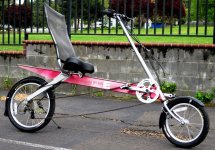
It's starting to look like a bike again. I have it all put back together for regular riding and have done a few upgrades. Better brakes, different brake levers to accommodate the Magura throttle, and I found some fenders on Craigslist this week too. I also added a 52 tooth chain ring to the front. Now I can either ride the stock 46 or switch by hand to the 52. Once it goes electric it will spend most of the time on the 52. Small handlebars! I'm going to have to get creative to have a bike computer and a light on the bars, and forget about using the stock drink holder mounts. That TOTALLY isn't going to happen. I have a couple of ideas though. :wink: The bike is a real pleasure to ride. SUPER comfortable, I just can't wait for pedaling to be optional. 8)

Rassy
1 MW
The Bike E is looking good. I still expect to be in Ashland two weeks from now and want to see it Motorized. 
I'll send you a PM before heading over.
I'll send you a PM before heading over.
StudEbiker
100 kW
I don't think two weeks to be motorized is realistic. I'm hoping for July. I'll look forward to visiting. I got to ride that Stealth Bomber last week. Friggin' sweet ride! 
StudEbiker
100 kW
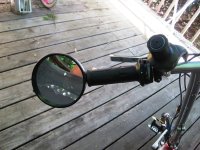
Most of the parts I need to finish this project (or at least get it on the road :wink: ) are here now. There' just a couple more things O need to get done before I can start putting all the electric bits on the bike. I am very excited to get it on the road. This Bike E draws more attention going down the road than any vehicle I've ever driven. In the 30 miles I've ridden it so far around town I've had about eight people yell to me, "Nice bike!"  Yesterday I was at a yard sale and found a couple of decent motorcycle mirrors that I thought I might be able to adapt to the Bike E.
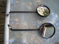
I cut the shaft down on one today.
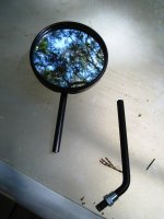
And then I drilled some holes in a couple of bar end caps to slide the shaft on to and then slipped everything into the end of the bar. It works great. Fully adjustable, quality glass mirror with very little vibration distortion going down the road. I'll wait to see if I want one on the other side after I use this one a bit.

I cut the shaft down on one today.

And then I drilled some holes in a couple of bar end caps to slide the shaft on to and then slipped everything into the end of the bar. It works great. Fully adjustable, quality glass mirror with very little vibration distortion going down the road. I'll wait to see if I want one on the other side after I use this one a bit.

StudEbiker
100 kW
Finally got to spin the motor for the first time today. Thanks to Fechter and others for posting the how-tos on matching motors and controllers. I ended up getting it right on about the third try!!
[youtube]DwJfBxwwMmY[/youtube]
[youtube]DwJfBxwwMmY[/youtube]
wineboyrider
1 MW
Glad to see you got that schweet motor working with the controller. Are you going through the gears or left side drive?
8) 8)
8) 8)
StudEbiker
100 kW
Through the gears, Sachs 3x7 rear hub.
wineboyrider
1 MW
Awesome! My friend had a Bike E and it was a really nice comfortable ride should be a keeper if done right.
8) 8)
8) 8)
StudEbiker
100 kW
I had a nice sunny day in Ashland today for a change. It was a great day to work on the Bike E. As the motor mounting plates haven't made it back from the shop yet there wasn't much to do on the bike itself so I decided to go ahead and figure out the mounting arrangement for the bob trailer. Hooking it up went very smooth and I am really pleased with the way it trails behind the bike. Can't wait to carry some heavy loads (like groceries!) with it.View attachment 2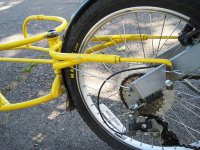


StudEbiker
100 kW
wineboyrider
1 MW
This is going to be cool to see. I love the Bike E. 8) 8) 8)
Similar threads
- Replies
- 8
- Views
- 561
- Replies
- 6
- Views
- 707


