• Hello ES! We could use some help to get us past the finish line on building the new knowledgebase for the forum.
    Can you donate? Please see our fundraising page. Thank you!

SUNRA ROBO-S Battery Lockout and BMS Protocol Help Needed

My friend [amico] Very interesting approach.Bravo......

For many months I've been investigating the SUNRA ROBO-S architecture and I'm slowly reaching the same conclusion: the real mystery may not be the battery cells themselves, but the communication between the BMS and the controller.

My own measurements revealed severe cell-group imbalance and some questionable protection behavior from the original battery system. This raised an important question: is the scooter reacting to actual battery conditions, or to the information reported by the BMS?

Your ESP32 man-in-the-middle idea is therefore extremely interesting. Before replacing hardware, it makes sense to first understand what information is actually exchanged on the communication bus.

I am particularly interested in whether the controller only reads voltage, current and SOC, or whether it also expects specific status flags, error codes, counters, or other proprietary messages from the BMS.

If you manage to capture and decode the protocol, I believe it could answer many questions not only for your scooter but for all of us trying to understand how much of the SUNRA ecosystem depends on BMS-controller communication.

Please keep us updated with any logic analyzer captures, baud rate findings, frame structures, CRC details, or protocol observations. I think many owners are following this topic with great interest.

Greetings from Greece.
Thank you for this excellent post.

On one side, we have the manufacturer telling owners that the solution is simply to buy a new battery for a very significant amount of money.

On the other side, we have a growing community of owners trying to understand what is actually happening inside these systems, because many of us believe that knowledge, transparency and repairability should come before expensive replacement.

Your approach is the first one I've seen that goes beyond "replace the battery" and starts asking the real engineering questions about communication, protocols and system integration.

Many ROBO-S owners are currently stuck between expensive OEM solutions and a complete lack of technical documentation. The international community seems to have very little information to share so far.

If your investigation succeeds, it may help not only one scooter, but many owners facing the same situation.

So please keep us updated. Your work could shine some light into a very dark corner of these proprietary systems.

And speaking as a frustrated ROBO-S owner: before we all push our scooters off a cliff, we're hoping that people like you might help us understand what's really going on inside them.

Good luck, and thank you for taking the time to explore this.
 
Hello Voultepsis,

Thank you so much for your detailed reply — it's genuinely
encouraging to find another SUNRA ROBO-S owner who has reached
the same conclusion about BMS-to-controller communication being
the real "black box" of this system. Your question — "is the
scooter reacting to actual battery conditions, or to the
information reported by the BMS?" — is exactly the working
hypothesis I want to test.

CURRENT STATUS OF MY INVESTIGATION

I've used the connector of one of the two batteries to start
identifying how it communicates with the controller. Two pins
clearly carry a digital signal, and I'm currently working to
determine the exact baud rate using my oscilloscope (Rigol
DHO804). Before starting the systematic frame capture, I want
to share an important observation I had:

A KEY ADVANTAGE I JUST REALIZED

Having TWO batteries on the same bus — one apparently healthy
and one incorrectly reporting 0% SOC — is essentially a built-in
A/B test for protocol decoding. By comparing the two BMS
responses side by side within the same polling cycle, I should
be able to immediately identify:

- Protocol constants (bytes identical between both BMS): header,
function code, length field, magic bytes
- The SOC byte/word (drastically different: ~87% healthy vs 0%
faulty)
- Any active status flags or error bitfields uniquely set by
the faulty BMS
- Any enumerated error codes populated by the faulty pack
- The position and structure of the CRC/checksum

In other words, a single capture session could reveal most of
the protocol structure, because the faulty BMS acts as a
"natural trigger" for error conditions — I don't need to
artificially induce them.

QUESTIONS FOR YOU

- Have you ever captured any bus traffic, even with just a
scope or logic analyzer? Even a 30-second sample would be
extremely valuable for cross-validation between our two bikes.
- Have you ever tried disconnecting the BMS communication line
entirely (leaving only the power connection)? It would be
useful to know how the scooter behaves with no BMS data at
all — that would give us a useful baseline.

NEXT STEPS ON MY SIDE

- Confirm the baud rate (cursor measurement on a single bit)
- First full Event Table capture from the oscilloscope, exported
as CSV
- Draft byte-by-byte mapping of the frame structure
- CRC algorithm analysis (likely Modbus CRC-16 or XOR — to be
determined)
- I'll post raw captures and decoded findings as soon as I have
them.

Thanks again for engaging — it's genuinely motivating to find
someone tackling the same problem with the same investigative
approach.
 
Hello Voultepsis,

Thank you so much for your detailed reply — it's genuinely
encouraging to find another SUNRA ROBO-S owner who has reached
the same conclusion about BMS-to-controller communication being
the real "black box" of this system. Your question — "is the
scooter reacting to actual battery conditions, or to the
information reported by the BMS?" — is exactly the working
hypothesis I want to test.

CURRENT STATUS OF MY INVESTIGATION

I've used the connector of one of the two batteries to start
identifying how it communicates with the controller. Two pins
clearly carry a digital signal, and I'm currently working to
determine the exact baud rate using my oscilloscope (Rigol
DHO804). Before starting the systematic frame capture, I want
to share an important observation I had:

A KEY ADVANTAGE I JUST REALIZED

Having TWO batteries on the same bus — one apparently healthy
and one incorrectly reporting 0% SOC — is essentially a built-in
A/B test for protocol decoding. By comparing the two BMS
responses side by side within the same polling cycle, I should
be able to immediately identify:

- Protocol constants (bytes identical between both BMS): header,
function code, length field, magic bytes
- The SOC byte/word (drastically different: ~87% healthy vs 0%
faulty)
- Any active status flags or error bitfields uniquely set by
the faulty BMS
- Any enumerated error codes populated by the faulty pack
- The position and structure of the CRC/checksum

In other words, a single capture session could reveal most of
the protocol structure, because the faulty BMS acts as a
"natural trigger" for error conditions — I don't need to
artificially induce them.

QUESTIONS FOR YOU

- Have you ever captured any bus traffic, even with just a
scope or logic analyzer? Even a 30-second sample would be
extremely valuable for cross-validation between our two bikes.
- Have you ever tried disconnecting the BMS communication line
entirely (leaving only the power connection)? It would be
useful to know how the scooter behaves with no BMS data at
all — that would give us a useful baseline.

NEXT STEPS ON MY SIDE

- Confirm the baud rate (cursor measurement on a single bit)
- First full Event Table capture from the oscilloscope, exported
as CSV
- Draft byte-by-byte mapping of the frame structure
- CRC algorithm analysis (likely Modbus CRC-16 or XOR — to be
determined)
- I'll post raw captures and decoded findings as soon as I have
them.

Thanks again for engaging — it's genuinely motivating to find
someone tackling the same problem with the same investigative
approach.
My itallian friend.
Hello,

Thank you for your detailed reply and for sharing your investigation. Your approach is very interesting and I believe we are exploring many of the same questions regarding the ROBO-S system.

Over the past months, I have also gathered a number of observations and findings from my own scooter. Some of these may be relevant to your work, but for the moment I would prefer not to discuss certain details publicly while we are still evaluating and validating our conclusions.

If you are interested, I would be happy to continue part of this discussion by email and exchange information directly.

My email is: pavoult@gmail.com

Perhaps it would be useful for us to compare findings privately until we have correlated our results and gained a clearer understanding of the BMS-controller communication and overall system behavior.

I look forward to hearing from you.

Best regards,

Voultepsis Paul
 
My friend [amico] Very interesting approach.Bravo......

For many months I've been investigating the SUNRA ROBO-S architecture and I'm slowly reaching the same conclusion: the real mystery may not be the battery cells themselves, but the communication between the BMS and the controller.

My own measurements revealed severe cell-group imbalance and some questionable protection behavior from the original battery system. This raised an important question: is the scooter reacting to actual battery conditions, or to the information reported by the BMS?

Your ESP32 man-in-the-middle idea is therefore extremely interesting. Before replacing hardware, it makes sense to first understand what information is actually exchanged on the communication bus.

I am particularly interested in whether the controller only reads voltage, current and SOC, or whether it also expects specific status flags, error codes, counters, or other proprietary messages from the BMS.

If you manage to capture and decode the protocol, I believe it could answer many questions not only for your scooter but for all of us trying to understand how much of the SUNRA ecosystem depends on BMS-controller communication.

Please keep us updated with any logic analyzer captures, baud rate findings, frame structures, CRC details, or protocol observations. I think many owners are following this topic with great interest.

Greetings from Greece.
Hi,


Quick update from today's tests.


I connected a ZLA031S isolated USB-RS485 adapter directly to the ROBO-S BMS communication connector.


The adapter is detected as COM11 and continuously receives data from the scooter. The RX counter exceeded 33,000 bytes during the capture, confirming constant bus traffic.


This screenshot was taken at 4800 baud, 8 data bits, 1 stop bit (see settings in the picture). The received data shows repeating byte patterns, although I have not yet identified valid frames or decoded the protocol.


Does this resemble what you're seeing on your setup?


Have you already identified the correct UART settings or are you still capturing raw traffic?
 

Attachments

  • parity None  4800.JPG
    parity None 4800.JPG
    1.2 MB · Views: 3
Hi Paul, excellent work.
Does this connector provide direct access to the battery communication bus?
Have you been able to identify the pinout and determine which pins are used for communication?
Could you tell me exactly where this connector is located on the scooter?
 

Attachments

  • Screenshot 2026-06-25 192924.png
    Screenshot 2026-06-25 192924.png
    200.2 KB · Views: 0
Hi,


Quick update from today's tests.


I connected a ZLA031S isolated USB-RS485 adapter directly to the ROBO-S BMS communication connector.


The adapter is detected as COM11 and continuously receives data from the scooter. The RX counter exceeded 33,000 bytes during the capture, confirming constant bus traffic.


This screenshot was taken at 4800 baud, 8 data bits, 1 stop bit (see settings in the picture). The received data shows repeating byte patterns, although I have not yet identified valid frames or decoded the protocol.


Does this resemble what you're seeing on your setup?


Have you already identified the correct UART settings or are you still capturing raw traffic?
Thinking about it more carefully, I would expect to see not only a repeating data stream. If the communication is master/slave, there should be a sequence where the master sends a request and, shortly afterward, the battery responds.

Did you notice any packets that look different from the others, possibly shorter request frames followed by longer response frames? Or does the battery appear to transmit data continuously on its own?
 
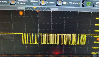
Hi everyone, sharing the progress of the last few weeks on reverse engineering the protocol between the controller and the BMS (Fish20S002 with dual BQ7693003).


Hardware setup (see pics): ESP32 DevKit v1 + a MAX485 module in passive mode, tapped in parallel onto the RS485 bus. Output via Bluetooth SPP to a PC, so I can log complete sessions.


Confirmed UART parameters:


  • 4800 baud
  • 8E1 (even parity — critical; with 8N1 I was only getting random-looking garbage)
  • Inter-byte gap up to 70 ms (the BMS is slow), so the frame timeout has to be set around 100 ms, not the classic Modbus 3.5 char-time

Observed structure:


  • Controller → BMS request: 3 bytes, 19 08 XX (so far I've seen 38 and FE, it changes depending on vehicle state)
  • BMS → controller response: 10 or 11 bytes, header 00 08 FC ...
  • Full polling cycle ~400 ms (2.5 Hz)

Attached an excerpt of the captured log and two scope screenshots (Rigol DHO804, 500 kSa/s, ~100 samples per bit).


The checksum mystery: the last byte of the response is deterministic (identical payloads produce the same checksum ~80% of the time), but:


  • Brute-forced all 256 CRC8 polynomials (× init × refin × xorout) → no match
  • Brute-forced CRC16 with 20 standard variants (Modbus, CCITT, Kermit, X25, USB...) → no match
  • Sum, XOR, two's complement → no match
  • The remaining 20%: identical payload produces a different checksum → I suspect a counter or internal state is folded into the calculation

Next step: I'm building a bidirectional MITM with two MAX485 transceivers to intercept and (later) modify the traffic. End goal: figure out why one of the two battery packs reads 0% SoC even though it's perfectly healthy, and possibly force the controller to recognize it.


Has anyone worked on King.co / Fish20S002 BMSes before, or recognizes the checksum pattern? Any pointers welcome.
 

Attachments

  • serial_20260629_160159.txt
    9.8 KB · Views: 1
  • Screenshot 2026-06-29 180016.png
    Screenshot 2026-06-29 180016.png
    1.2 MB · Views: 1
  • Screenshot 2026-06-29 180001.png
    Screenshot 2026-06-29 180001.png
    1.8 MB · Views: 1
  • Screenshot 2026-06-29 180048.png
    Screenshot 2026-06-29 180048.png
    510.7 KB · Views: 1
Excellent work, Castani. Thank you for sharing your findings. I also have a Sunra Robos with two Fish20S002 battery packs and I've been investigating the same problem. Your work is extremely interesting and I look forward to your next results.
 
Hi Paul, excellent work.
Does this connector provide direct access to the battery communication bus?
Have you been able to identify the pinout and determine which pins are used for communication?
Could you tell me exactly where this connector is located on the scooter?
hi Castani [amico] At this point I can't say for certain. I haven't investigated the original purpose of this 4-pin connector yet. What I can confirm is that it provides access to the communication bus, since I'm able to capture continuous RS485 traffic (4800 baud, 8E1) from that connector while the scooter is operating. Whether it is officially intended as a diagnostic/service connector or simply exposes the internal communication bus is still unknown.
 
Excellent work, Castani. Thank you for sharing your findings. I also have a Sunra Robos with two Fish20S002 battery packs and I've been investigating the same problem. Your work is extremely interesting and I look forward to your next results.
First of all, congratulations on your excellent reverse engineering work. Your findings about the communication parameters (4800 baud, 8E1) helped me reproduce the setup on my own scooter. Thank you for sharing your work openly.

At the moment I'm reproducing your communication settings (4800 baud, 8E1, RS485) and recording the traffic from my scooter.
The interesting part is that one of my battery packs appears to lose State of Charge on the dashboard much faster than the healthy pack, while the actual pack voltage remains very close. At the moment the difference between the two packs is only about 0.3 V, yet the dashboard reports a much lower SoC for the faulty pack.
I'm collecting communication logs at different displayed SoC levels so that later we can compare them and see which bytes change as the displayed percentage decreases.
 
First of all, congratulations on your excellent reverse engineering work. Your findings about the communication parameters (4800 baud, 8E1) helped me reproduce the setup on my own scooter. Thank you for sharing your work openly.

At the moment I'm reproducing your communication settings (4800 baud, 8E1, RS485) and recording the traffic from my scooter.
The interesting part is that one of my battery packs appears to lose State of Charge on the dashboard much faster than the healthy pack, while the actual pack voltage remains very close. At the moment the difference between the two packs is only about 0.3 V, yet the dashboard reports a much lower SoC for the faulty pack.
I'm collecting communication logs at different displayed SoC levels so that later we can compare them and see which bytes change as the displayed percentage decreases.
If you're interested, I'd be happy to exchange raw captures by email as well. It may be easier to compare logs and larger files that way, while we continue sharing general progress on the forum.
 
f you're interested, I'd be happy to exchange raw captures by email as well. It may be easier to compare logs and larger files that way, while we continue sharing general progress on the forum.
Thank you, Casiani.Amico


I'd be very happy to exchange raw captures by email.
I think this will make comparison much easier than using the forum.


I'll prepare my captures and send them to you.
We can continue posting our general findings on the forum so everyone can benefit.


Thank you again for your collaboration.
 
Back
Top