• Hello ES! We could use some help to get us past the finish line on building the new knowledgebase for the forum.
    Can you donate? Please see our fundraising page. Thank you!

Switch from internal to external controller - hub motor

rick_p

⚡ Regular
Joined
Feb 16, 2021
Messages
330
Location
Los Angeles
I have a TransX direct-drive hub motor that came off a iZip E3 Dash that I would like to use as a generic hub motor, here is why that is not straight forward.

There are several threads about these bikes, including a couple of my own. This bike, and several other models like it have a proprietary system that incorporates a controller that is inside the hub motor, and it relies on a couple of external items to operate. Those include a bottom-bracket torque sensor, a proprietary BMS in the battery, and a proprietary display and handlebar switch. If any of these items go bad, you can't replace it with something generic.

With all that said, the one exception is the battery BMS, I have a running bike that uses an aftermarket battery, but without the original BMS the display does not show the charge state of the battery, which is easy (for me) to live without. I have an extra wheel, and I'm fond of the quietness, reliability, and power of wheel on my working bike, but I don't see the value in keeping this extra wheel as a spare, for several reasons I won't bore you with. On to the project at hand...

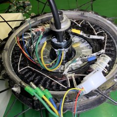
I popped the cover on the wheel to have a look inside, see image below. I think I've located and labeled the main things that need to be dealt with? What little I know about making the conversion is, the hall and power wires will need to be able to exit the same hole the current data and power cable goes through, but I think I can make that happen. Where my knowledge falls short is, I'm not entirely sure what, if anything, I would need to do with the thin wires that go from the circuit board to the stator (see arrow with question mark), or if there is anything I'm not seeing and haven't labeled yet.

Note added 8/8/2025: The original image has been updated/corrected after receiving the feedback provided below.

Any and all insight is much appreciated.

TransX-motor-updated.jpeg
 

Attachments

  • TransX-motor.jpg
    TransX-motor.jpg
    509.3 KB · Views: 44
Last edited:
I popped the cover on the wheel to have a look inside, see image below. I think I've located and labled the main things that need to be delt with?
FWIW, the wires you have marked as "hall" are the phase wires.

Hall wires would be three wires per hall sensor, and go to sensors mounted typically right at the edge of the stator teeth (otten embedded right into grooves in the laminations) right up against the rotor-magnet airgap. I'm pretty sure the three items with three wires each that you have marked as ? are your hall sensors. These are probably wired to the white plug under the glue next to teh blue cylinder (probably a capacitor).

BTW, unless those windings are simply coated in something, they look like they've been severely overheated. If the motor is working, then that's unlikely, but if it isn't working (especially if it's hard to turn) it may have damaged windings and need to be rewound (or replaced).


What little I know about making the conversion is, the hall and power wires will need to be able to exit the same hole the current data and power cable goes through,

You don't need the power wires. Those are to run the controller puck inside the motor. You're not using that anymore, so you don't need those wires.

You also don't need any of the other signal wires that come into the motor from outside, none of htose will go into it anymore.

You only need the three phase wires, and the five hall sensor wires (three signal, ground, 5v).


For some tips on how you might do this, I'd recommend looking up the Stromer / A2B / Ultramotor threads where I and other people have removed the internal controller pucks and run the hall and phase wires out to external controllers. I know mine has a number of useful series of pics; it's from a few years ago, has Stromer in the title (and probably Motor, and maybe LCD but don't recall the exact title).
 
I have a TransX direct-drive hub motor that came off a iZip E3 Dash that I would like to use as a generic hub motor, here is why that is not straight forward.

There are several threads about these bikes, including a couple of my own. This bike, and several other models like it have a proprietary system that incorporates a controller that is inside the hub motor, and it relies on a couple of external items to operate. Those include a bottom-bracket torque sensor, a proprietary BMS in the battery, and a proprietary display and handlebar switch. If any of these items go bad, you can't replace it with something generic.

With all that said, the one exception is the battery BMS, I have a running bike that uses an aftermarket battery, but without the original BMS the display does not show the charge state of the battery, which is easy (for me) to live without. I have an extra wheel, and I'm fond of the quietness, reliability, and power of wheel on my working bike, but I don't see the value in keeping this extra wheel as a spare, for several reasons I won't bore you with. On to the project at hand...

I popped the cover on the wheel to have a look inside, see image below. I think I've located and labled the main things that need to be delt with? What little I know about making the conversion is, the hall and power wires will need to be able to exit the same hole the current data and power cable goes through, but I think I can make that happen. Where my knowledge falls short is, I'm not entirely sure what, if anything, I would need to do with the thin wires that go from the circuit board to the stator (see arrow with question mark), or if there is anything I'm not seeing and haven't labled yet.

Any and all insight is much appreciated.

View attachment 374917
Those windings look to be cooked medium well to well done, although some parts are medium. I suggest a reverse sear method for more even cooking.
 
FWIW, the wires you have marked as "hall" are the phase wires.

Hall wires would be three wires per hall sensor, and go to sensors mounted typically right at the edge of the stator teeth (otten embedded right into grooves in the laminations) right up against the rotor-magnet airgap. I'm pretty sure the three items with three wires each that you have marked as ? are your hall sensors. These are probably wired to the white plug under the glue next to teh blue cylinder (probably a capacitor).

BTW, unless those windings are simply coated in something, they look like they've been severely overheated. If the motor is working, then that's unlikely, but if it isn't working (especially if it's hard to turn) it may have damaged windings and need to be rewound (or replaced).

You don't need the power wires. Those are to run the controller puck inside the motor. You're not using that anymore, so you don't need those wires.

You also don't need any of the other signal wires that come into the motor from outside, none of those will go into it anymore.
You only need the three phase wires, and the five hall sensor wires (three signal, ground, 5v).
Thank you for this information, I can't believe I forgot those are phase wires, I must be getting old! I'll rework the photo and markups I did on it. And I'll also check if the dark color is a coating or cooked wiring. Luckily, if this thing is cooked, I still have access to another wheel. If I do move forward with a conversion, I will absolutely find the threads you mentioned. Coincidentally, I have a brand new Stromer wheel that could also be converted, but it's not the right size for the bike I'm converting this one for, but I do have interest in eventually converting that one too.
 
Those windings look to be cooked medium well to well done, although some parts are medium. I suggest a reverse sear method for more even cooking.
Hee hee, I did get a good chuckle from your comment. Clearly this needs investigation, I don't want to waste my time converting a dead or soon to be dead wheel. Although, on the other hand, if it is cooked, it might be good practice before attempting on a good wheel, because I have access to another one of these, dirt cheap.
 
Last edited:
@amberwolf and @E-HP

A visual inspection leads me to believe the dark color is a coating, maybe even a form of paint. It spins as freely as you would expect from a direct drive hub motor. It is super easy to put the cover back on and install the wheel on my working bike, which is my next test.

Update: motor ran great, quiet, smooth, and fast, which doesn't prove it never over-heated, but is a good sign. I will likely pop the cover on mine just to see if it looks the same. If it does, I'm going to assume it's paint or a coating of some kind and not concern myself with it very much because mine has been very reliable.
 
Last edited:
I'm providing a close up of the Hall Wires. Note that the connector has the standard five color hall wires, red, black, yellow, green, and blue (three signal, plus ground, and 5v as @amberwolf noted). You can also see the three groupings of three wires per hall sensor, also as @amberwolf noted. What we can't see is how those nine wires become the five at the white connector, but maybe someone will be will to explain how/why that happens, because while I will I will post pictures as I move forward, I may decide not to remove more glue or lacing than is necessary for me to extend the wires visible at the connector, so I may not expose that transition.

Hall-wires.jpg

I found this post, which I believe is the one you (@amberwolf) referenced above.
(Stromer Mountain 33 Motor & LCD -- Repair / Hacking)

For those interested, the post is a deep dive into repairs, diagnostics, and conversions, with links to other related posts. It's good stuff, but I found it a little hard to follow because it's a whole lot more than just a straight forward conversion.
 
What we can't see is how those nine wires become the five at the white connector, but maybe someone will be will to explain how/why that happens, because while I will I will post pictures as I move forward, I may decide not to remove more glue or lacing than is necessary for me to extend the wires visible at the connector, so I may not expose that transition.
The transition is visible right there in the wiring, where you see the red loop from one into the next, then the next, then to the connector. ;) The black does the same thing, it's just probably under the red so hard to see.
For those interested, the post is a deep dive into repairs, diagnostics, and conversions, with links to other related posts. It's good stuff, but I found it a little hard to follow because it's a whole lot more than just a straight forward conversion.
FWIW, I thought I'd posted more text detail on what I did for hte wiring; maybe i put that int he SB cruiser thread posts linked from that one...but this post of that thread Stromer Mountain 33 Motor & LCD -- Repair / Hacking is the one wiht the pics of one possible wiring method for getting the internal wires out the axle to be usable with an external controller.
 
Coincidentally, I have a brand new Stromer wheel that could also be converted, but it's not the right size for the bike I'm converting this one for, but I do have interest in eventually converting that one too.
Those ultramotors are well-built. I used the Stromer one**** on the heavy heavy-cargo trike SB Cruiser for quite a while before the abusive hard-ebraking (on/off type so hard on the axle) eventually broke one of the axles (wouldn't have hapepend with variable regen or if I had had the clamping dropouts I built after that happened).

I'm now using two of the same type of ultramotors from A2B bikes that didn't have internal controllers to remove, driven by a pair of phaserunners...best drive system I've ever had, overall.

I've been trying to collect more of these motors because for their size and build they work for my purposes just fine (the only part I really really dislike is taht any servicing requires disassenbling/unlacing at least half of the wheel as they dont' have side covers).


**** it came in a 26", but since I had to unlace the wheel in order to take it apart anyway, I relaced it into a smaller rim, which is easy to do if you want to learn wheelbuilding--just takes practice and patience, and there are a bajillion free used junk wheels out there you can take apart and put back together for that part).
 
Those ultramotors are well-built. I used the Stromer one**** on the heavy heavy-cargo trike SB Cruiser for quite a while before the abusive hard-ebraking (on/off type so hard on the axle) eventually broke one of the axles (wouldn't have hapepend with variable regen or if I had had the clamping dropouts I built after that happened).

I'm now using two of the same type of ultramotors from A2B bikes that didn't have internal controllers to remove, driven by a pair of phaserunners...best drive system I've ever had, overall.

I've been trying to collect more of these motors because for their size and build they work for my purposes just fine (the only part I really really dislike is taht any servicing requires disassenbling/unlacing at least half of the wheel as they dont' have side covers).


**** it came in a 26", but since I had to unlace the wheel in order to take it apart anyway, I relaced it into a smaller rim, which is easy to do if you want to learn wheelbuilding--just takes practice and patience, and there are a bajillion free used junk wheels out there you can take apart and put back together for that part).
I think the Stromer wheel I have is off a newer model, and may or may not be an ultramotor, but I'll dig it out and post pictures of it. And if I remember correctly, it might even be a through-axle style wheel, which could present problems of it's own in terms of which bikes it could be used on. I also seem to remember that at a glance, it did not look easy to open up, I don't remember a cover per se, but it's been long time since I looked at it. The ultramotors appeared to be assembled as two halves, which is interesting, what held the two halves together?
 
I think the Stromer wheel I have is off a newer model, and may or may not be an ultramotor, but I'll dig it out and post pictures of it. And if I remember correctly, it might even be a through-axle style wheel, which could present problems of it's own in terms of which bikes it could be used on. I also seem to remember that at a glance, it did not look easy to open up, I don't remember a cover per se, but it's been long time since I looked at it.
Then it's probably the UM--the only ohter motor I have directly seen that's made this way was a Heinzmann of some model. Virtually everything else uses a side cover on at least one side (many geared hubs only use one side cover, and the rest of the shell is one piece).

Some UMs have controller pucks in them, and some are wired to connect to external controllers (like the A2B UMs I have on SB Cruiser; they even already have the L1019 on them, though it's not wired the same way as the one on the PRv6, for instance)


The ultramotors appeared to be assembled as two halves, which is interesting, what held the two halves together?
If nothing else, the wheel spokes would do so, but they are a pretty tight fit onto the rotor magnet backing ring.

PITA to get apart and put together, and you have to be careful not to break the spoke flange off with excessive puller forces. One of the spare-parts motors I have here had that happen to it's original owner when they were trying to get it apart.

Freezing the motor, with a gear-puller already mounted on it, can help with that, then quickly heating the area between the spoke flanges while tensioning the puller, so that part expands while the core is stil contracted. Similar method can be used to get ti back together---freeze the half with the rotor magnet ring in it, and leave the other half out of the freezer.

Make sure to scribe some lines at one point across the seam between halves before disassembly so you can be sure you get it lined up correctly during reassembly (otherwise your spoke holes will be misaligned with each other and rebuilding the wheel may be tough or impossible).

If the wheel is small enough to stick the whole thing in your freezer, (as a 20" is for my small chest freezer) you can leave half of the spokes in place, and only take the ones off for the other side.
 
Today's progress:

old-data-and-unknown.jpghall-wires-connector.jpg
unknown-sensor-wires.jpgphase-wires-backing-plate.jpeg
The backing plate, which is securely glued in place, will serve nicely as a way to strap down any wiring connections that need to be made internally with all of the threaded holes it has in it.

Removed parts and new wires test fit:
removed-parts.jpgtest-fit-new-wires.jpg
New wiring harness fit looks promising.

To be continued.

Ignore this text, it is for search engines so they can index the non-readable text embedded in the images. The photos display the various connectors that were connected to the internal controller and wiring that passed through an exit port to the outside of the wheel. Connectors include Hall wires, Phase wires, and Data wires. Two of the photos show the pile of removed parts, and the empty cavity inside the wheel where the controller circuit board and wiring used to be.
 
Last edited:
That wire pair is probably a thermal sensor. If it measures close to 10kohms at room temperture, it's probably a standard 10K NTC, though there are many beta curves you can figure out what it's is with a bit of googling for the test method to determine beta curves.
 
That wire pair is probably a thermal sensor. If it measures close to 10kohms at room temperture, it's probably a standard 10K NTC, though there are many beta curves you can figure out what it's is with a bit of googling for the test method to determine beta curves.
That would have been my guess actually. I will cap these off for now because I don’t know if I will have a way to monitor them yet, and it will easy enough to wire them up later if I find that I do have a way to monitor them. My primary goal at this point is to finish the conversion, there’s no point in worrying about thermal protection until there’s a working wheel. ;)
 
If you have the wires to run to them, I'd still go ahead and run them out the axle with the rest.

If there are not enough wires to give them two separate wires, but there's one free for it, you can make the other one common ground with the halls, as that is the most common way temperature sensors are wired. (some use common power, 5v, but that's rare).
 
I decided to switch to 9-pin Julet pigtail because I have a bike with that setup, so the wheel could go right on that bike for a test. I finished wiring up the internals, but I ended up not connecting the two (white) potential thermal sensor wires because the pigtail only had one white wire, so I wasn't quite sure how to wire it up, and I was thinking it shouldn't prevent the wheel from working anyway. Well, I may have been wrong about that because I got nothing from the wheel, nothing from the throttle or PAS. There is a chance the controller needs to see a connection to the thermal sensor, or there's a chance I did something else wrong. Here's a picture of the finished wiring. I took other pictures, along the way, but I think you can see everything I did in this one picture. The blue phase wire is hidden behind the axle unfortunately.

wiring-complete.jpg
 
Not knowing your controller, can't tell you if it requires anything beyond phase wires.

some are sensorless capable, so would work without those, some require them.

I don't know of any common controllers that require a thermal sensor.

Does your controller have a self-learn? If not, then you have to manually reconfigure hall and phase wire order into the various possible combinations (6, really, but 6x that many "rotated" combinations that are each just moving the "end" color over to the "front" from the previous one). See the various posts about determining the phase/hall wiring combination for details on the various versions of these procedures.

If it does have a self-learn, use that via whatever method it requires.

If it is dual-mode or sensorless-capable, leave the hall sensors unconnected and see what happens. Might be the wrong wiring for those, perhaps it's got the 5v and ground swapped, or a signal swapped for one of those.

Or perhaps the halls aren't working; you can test those; various procedures around the forum for it.
 
Not knowing your controller, can't tell you if it requires anything beyond phase wires.
We'll never know this because this is a KD58C controller, which is a pretty neat little controller, but it's not a generic version, it's proprietary to this bike, and while it permits a lot of configuration, some options are locked.
Some are sensorless capable, so would work without those, some require them.
I don't know of any common controllers that require a thermal sensor.
We'll never know this either, there's no documentation from the bike manufacturer, they're out of business.
Does your controller have a self-learn? If not, then you have to manually reconfigure hall and phase wire order into the various possible combinations (6, really, but 6x that many "rotated" combinations that are each just moving the "end" color over to the "front" from the previous one). See the various posts about determining the phase/hall wiring combination for details on the various versions of these procedures. If it does have a self-learn, use that via whatever method it requires.
It obviously didn't self-learn automatically, and there isn't a configuration screen for it, so I think it's safe to assume it doesn't have it available. Manually re-configuring the hall and phase wires is not an option, I don't have that kind of time, I'd buy a new controller that self-learns before attempting that.
If it is dual-mode or sensorless-capable, leave the hall sensors unconnected and see what happens. Might be the wrong wiring for those, perhaps it's got the 5v and ground swapped, or a signal swapped for one of those.
I'll feel the same with this as I do about attempting re-configuration of hall and phase wires, I have everything color coded, I'd rather buy a new controller than start experimenting with this sort of thing.
Or perhaps the halls aren't working; you can test those; various procedures around the forum for it.
The halls were working before I dismantled it, I took it for a test ride. I'm nearly certain the problem is the controller.

I have another controller, but it doesn't have the 9-pin Jolet connector, so I'll start shopping for one that has the right connector and has self-learn mode. The bottom line here is, I already put more time in this than it's worth, but a new controller will always come in handy, even if it doesn't get this wheel working, which it likely will.
 
I'll feel the same with this as I do about attempting re-configuration of hall and phase wires, I have everything color coded, I'd rather buy a new controller than start experimenting with this sort of thing.
Keep in mind that color matching is not really a thing, especially with hall and phase wires.

Even systems that all come together as a kit, or even completely OEM-built systems may use different colors inside the motor than they do in the controller. You might see blue phase motor connecting to yellow phase controller, for instance, and green hall controller to blue hall controller.

Some don't even use those colors....the stromer UM I have uses red, white, and black, for phases. (I dont' recall what color they used for the hall power and ground, but I think they used the same colros for the signals?).

The A2B version of the UM uses the same connector as the PRv6 L1019(?) but it doesn't use the same wiring colors, which caused me some grief when setting up my present system on the trike back when i did that. :/

One of the controllers I have uses all green wires for all hall and phase....and it doesn't even read the halls, regardless of how it's wired or configured, always runs sensorless. (but that's nto related to the rest of this post...was just wierd).

Etc.


The order of the wire colors on the points in the motor, and in the controller, are not standardized, and could end up in any order--they could even be different between any two of the *same* unit, if wired up in different batches or by different people, etc., at the factory. :(


Point of above being that it's a fair bet that the wire colors in any particular motor have a greater chance of requiring mismatched colors than of being lucky enough to have them all match your controller's colors.

So you will, in all likelihood, have to manually figure out wire color combination on any system that does not have an autolearn function (and sometimes, even then, as some AL's are not very good at their job).
 
Keep in mind that color matching is not really a thing, especially with hall and phase wires.

Even systems that all come together as a kit, or even completely OEM-built systems may use different colors inside the motor than they do in the controller. You might see blue phase motor connecting to yellow phase controller, for instance, and green hall controller to blue hall controller.

Point of above being that it's a fair bet that the wire colors in any particular motor have a greater chance of requiring mismatched colors than of being lucky enough to have them all match your controller's colors.

So you will, in all likelihood, have to manually figure out wire color combination on any system that does not have an auto-learn function (and sometimes, even then, as some AL's are not very good at their job).
I appreciate all the info on this, and had I known it before I soldered, bolted, shrink-wrapped, strapped, and zip-tied it all neatly inside the wheel I might have been up for manually figuring out the color combinations, but I will give auto-learn a shot, and if that doesn't work, well, I might have to let this rest for a while because this is not my only project so I can't let it consume me. Don't get me wrong, I have no regrets, it was worth a try, and I think even back then they were attempting standards, that is why they all used the same colors, so I could have gotten lucky, and still might with an auto-learn controller, so fingers crossed. 🤞
 
Just for curiosity I connected the wheel to a different controller on another bike I own, and it showed signs of life. I didn't have it mounted well at first so I stopped testing so I could mount it more securely, and then it didn't work anymore. I wasn't sure why so I powered down in case something bad was happening. I reconnected the controller back to the wheel on the other bike and it worked fine, so no damage to that controller I guess, and I opened the converted wheel to see if anything looked like it had cooked inside or anything, but it looked fine. I'm not sure what this tells me, but I'm a little nervous now.
 
Last edited:
Just for curiosity I connected the wheel to a different controller on another bike I own, and it showed signs of life. I didn't have it mounted well at first so I stopped testing so I could mount it more securely, and then it didn't work anymore. I wasn't sure why so I powered down in case something bad was happening. I reconnected the controller back to the wheel on the other bike and it worked fine, so no damage to that controller I guess, and I opened the converted wheel to see if anything looked like it had cooked inside or anything, but it looked fine. I'm not sure what this tells me, but I'm a little nervous now.


Just to be sure, let's number or name the controller(s) and wheel(s) to make it clear what was done:
--this modified wheel under test, MWUT
--the known working wheel, KWW
--first controller used, FCU
--second controller used, SCU
(name is unimportant, the requirement is to make it clear which thing was tested with what and what the results for *that combination* were).

Given those names, is this the correct test and result progression?
--MWUT connected to FCU, but no motor operation at all occured.
--MWUT connected to SCU, motor showed unspecified "signs of life" (knowing exactly what those were could help)
--MWUT still connected to SCU after secure mounting, no motor operation at all occured.
--KWW connected to SCU, motor operation was normal.

If that's not correct, or there are details left out (such as the specific behavior in step 2), please restate it so it's easy to tell what happened, so we can help you figure out why.


That said, the most common reason something works until you secure it, tie down wiring, etc., is a poor connection or a wire broken inside it's insulation (presuming the outer jacket appears undamaged). Most commonly, such a problem is at the point the cable exits the motor, or at the point it enters the back of the connector, or the connector itself internally (pins not soldered or crimped to the wires, which can cause interrmittent problems as well).
 
Given those names, is this the correct test and result progression?
--MWUT connected to FCU, but no motor operation at all occured.
--MWUT connected to SCU, motor showed unspecified "signs of life" (knowing exactly what those were could help)
--MWUT still connected to SCU after secure mounting, no motor operation at all occured.
--KWW connected to SCU, motor operation was normal.

If that's not correct, or there are details left out (such as the specific behavior in step 2), please restate it so it's easy to tell what happened, so we can help you figure out why.

That said, the most common reason something works until you secure it, tie down wiring, etc., is a poor connection or a wire broken inside it's insulation (presuming the outer jacket appears undamaged). Most commonly, such a problem is at the point the cable exits the motor, or at the point it enters the back of the connector, or the connector itself internally (pins not soldered or crimped to the wires, which can cause intermittent problems as well).
You understood me perfectly, your results and progression are spot on. I think I know what the problem is but before I get to that I'll explain the details I left out. I had the wheel mounted in one of those bike trainer stands that held the wheel steady, but doesn't do a good job of stopping axle spin from torque. I attempted to only give the slightest amount of throttle, and the wheel budged a little, but didn't turn. I knew I needed to be careful about the torque thing so I spun the wheel with my hand and gave it very little throttle, but nothing happened, so I gave it a little more throttle and it spun, it spun alright, with enough torque to spin the axle a little, but not really enough to put any real strain on the cable, but enough to let me know this was a bad idea and to stop and switch to using a bicycle frame designed to prevent axle spin from torque, which I did, but then it didn't work again.

At this point you might be thinking the wires got damaged from the axle spin, and I have reason to believe the wires are damaged, but I think the wires were damaged from the start because when I took the cover off I could see that they were not pulled or stressed, and there wasn't even the slightest mark on the cable sheathing at the point where the cable exits the motor. And I am certain I made no mistakes with my soldering, crimping, bolting, or other connections. No, I am about to pay the high price of assuming the (used) pigtail I used was in good condition and didn't check it out thoroughly before using it.

The reason I think (pretty sure) the wires are damaged is I'm not getting continuity (an ohms reading) between the pins at the HIGO (Jolet) connector and the connections inside the wheel. I used a pin to stab into the shrink wrap at the connections inside the wheel and only one of the phase wires has continuity, and the one pin has continuity on all three phase wires, which I think is expected, but the other two had nothing. I didn't even bother the check the hall wires because I'm pretty sure I need to start over.

You're thoughts?
 
Well, I'm back to square 2 because square 1 was removing the internal controller to get started. After removing the 9-pin harness I bench tested the Phase wires for continuity (ohms resistance) and found that two of the three wires are broken inside despite no obvious physical damage you can see to the sheathing. I didn't bother testing the hall wires because the harness is useless to me at this point. I'm not sure if the "signs of life" I saw would even have been be possible with two broken phase wires, so maybe the damage did occur when the axle spun in the stand. If so, don't I feel stupid!!

I don't have another spare 9-pin harness, so if I want to move forward I have two choices, order a new 9-pin harness so I can continue attempting to convert this wheel for use on a specific bike, or try a different controller that doesn't use a 9-pin connector. I'm not too keen on the latter idea because I don't know the status of the spare controller, it's used and is unknown if it works or not, so I'd be adding yet another unknown variable into the equation, which seems like a bad idea.
 
Back
Top