The care and feeding of a123-based packs...

GGoodrum said:
I'm not a big fan of the DeWalt chargers. I have four of them that I used to charge 8 packs. I recently re-did these into two 10s4p packs, as described earlier in this thread. Before I took the 8 packs apart, I put all on on the DeWalt chargers, and left them on for half-an-hour after the 3 lights first came on, just to make sure they were well-balanced. When I got the packs apart, and I was able to check the voltage of each cell, I was quite surprised at how out-of-balance they were. Almost every pack had cells that ranged from about 3.40 to 3.70V. In one pack, one cell was at 3.36V and another at 3.78V. They were so out-of-whack that I thought maybe some of the cells were stressed, and had lost capacity. They weren't, though, as I was able to balance the pack using a TP-210V balancer and then charge these back up using a TP-1010C charger and the cells are all very close now.

Maybe I just have four bad chargers, but I think that's highly unlikely. Anyway, I'm done with the DeWalts. :)

-- Gary
From my experience the Dewalt chargers are even worse than that.

Charge a pack up then discharge one cell to about 29-volts. Using just the Dewalt charger that pack will never be good for more than a few minutes of use. The charger will never balance it and that cell will trigger the LVC very quickly. (Leave these packs sit on the shelf for a while and this condition seems to happen often.)

Junk.
 
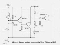
How about adding cell balancing to the BMS boards you've made GGoodrum? Recently poking around the web I found the attached circuit. It's a cell by cell shunt regulator that clamps the maximum cell voltage, and uses an opto-isolator to signal it's status. A bit of simplifying and it'd likely fit on the existing BMS boards.

hope this helps,
Marty

P.S. source link http://www.metricmind.com/ac_honda/main2.htm click on the "battery management system" link at the left, and enjoy.
 

Attachments

  • battery clamper.jpg
    battery clamper.jpg
    17.2 KB · Views: 5,899
Wow! good info for this schematics! the guy has been have an interesting project!

Just by combinating that to the LVC made by Bob and the PBC realized by GGoodrum would finally close that debate about the best way to charge and protect LI-ion !!

Doc
 
Doctorbass said:
Just by combinating that to the LVC made by Bob and the PBC realized by GGoodrum would finally close that debate about the best way to charge and protect LI-ion !!

Doc

Yes, that would be nearly idiot proof. Each circuit would need two optocouplers, one for charge, one for discharge. It should be relatively easy to interface the optocoupler outputs to a charger.
 
lawsonuw said:
How about adding cell balancing to the BMS boards you've made GGoodrum? Recently poking around the web I found the attached circuit. It's a cell by cell shunt regulator that clamps the maximum cell voltage, and uses an opto-isolator to signal it's status.

Looks like he's not using A123 chemistry, so will this circuit need modding to limit to 3.6V rather than the typically higher voltage of Li-Ion?
 
lawsonuw, you want to check out Jeff's "BMS package for A123 cells" thread here: http://endless-sphere.com/forums/viewtopic.php?t=2387

It features an improved version of the MetricMind BMS schematic, with SMT components sized just right for the A123 cells.

IF someone combines this with Bob's LVC circuit, I would buy 10 of them in a second. If not, I may have to build my own. Hmmm...
 
I'm still trying to decide if it is better to have balancing logic in the pack, or if this should be external. For one thing, I know the LVC circuit draws about what the cells will loose just sitting on the shelf, but can the same be said for a more complex clamp circuit? Can you leave this connected all the time?

-- Gary
 
:oops: looks like I brought up a fairly well know circuit.

brandonh said:
lawsonuw, you want to check out Jeff's "BMS package for A123 cells" thread here: http://endless-sphere.com/forums/viewtopic.php?t=2387

It features an improved version of the MetricMind BMS schematic, with SMT components sized just right for the A123 cells.

I wouldn't say "improved" so much as "nearly identical" but with a typo or two in the schematic, and bit lower current draw when off.

"Bob's LVC" circuit is even simpler than this voltage clamper circuit so it should easily fit on the same board.

@dermot: yea a 3.6v cutoff should still work with this circuit, but it won't go much lower.

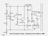
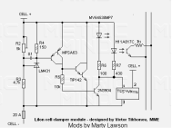
oh wow! adding the LVC circuit into the voltage clamper just requires adding the TC54VN to the right spot in the circuit. Using the same Opto-coupler/LED for the voltage clamp and LVC circuits works because it'd be crazy to have a pack with both fully charged cells still charging, and other cells that were totally dead. (see attached image)

Both of the "CELL +" terminals are connected together, I just couldn't think of a clean way to run that wire so I just used a label. Also, I added R1 to the output of the opto. This mod will allow an attached master controller to count how many cells have activated this circuit. (still can't tell who's active though, gotta look at the LED for that.)

Marty

P.S. look at the LVC circuit earlier in this thread for the pin labels of the TC54VNxxx part. I just did this in windows paint.
 

Attachments

  • cell by cell BMS for Li batteries.PNG
    cell by cell BMS for Li batteries.PNG
    27.6 KB · Views: 5,320
GGoodrum said:
I'm still trying to decide if it is better to have balancing logic in the pack, or if this should be external. For one thing, I know the LVC circuit draws about what the cells will loose just sitting on the shelf, but can the same be said for a more complex clamp circuit? Can you leave this connected all the time?

-- Gary

Makes for a much simpler charger circuit, just plug in a PSU and away you go. Means we would be able to sell the pack to average customers...
 
Jozzer said:
Makes for a much simpler charger circuit, just plug in a PSU and away you go. Means we would be able to sell the pack to average customers...

Maybe, but can you really leave this connected to the pack all the time? The TC54 voltage detector is a very low-power device. How much current does the clamping circuit draw when the pack is not being charged? Also, this still has quite a few parts, can it be simplified?

Normally, you would use a CC/CV charger with these cells, one that pumps in whatever the max current rating for the charger is until the voltage climbs up to about 3.7V per cell. Then it is held at that voltage while the current slowly drops off to the point it is about 10% of the max current, at which pont the cell is about as full as it is going to get. What, exactly, does this clamping action do, hold the voltage coming in to 3.7V? What about the current, will it "naturally" bleed off, or is some sort of other logic also required? I guess if this will simply limit the voltage per cell to 3.7V, or thereabouts, you could use a regular SLA CC/CV charger to do the "topping off" function. If this sort of circuit really does implement the CV part of the charging profile, that would allow the use of a basic lab supply as a charger.

Either way, if this won't draw too much power while "on-the-shelf", I would definitely be interested in doing a combo board, but it would be better if this might be simplified a bit more, to reduce the parts count.

-- Gary
 
I would like to thanks you GGoodrum for the great job you did about the LVC pcb that you have sent to me . Great packing, very clean pcb, that's Cool! :wink:

Here are some pics i toke after assembling those:

I will use 2 board for my existing 20s 4p setup and 2 next boards for my future konion pack 20s 16p of 2000Wh

Doc
 

Attachments

  • P1030459_800x600.jpg
    P1030459_800x600.jpg
    73.9 KB · Views: 6,559
ok, the standby current of the given circuit is about 0.5mA plus any leakages in the silicon parts. The circuit should still work just fine if the values of R2 and R3 are increased 10x to 100x. This mod would get the circuit into the ~10uA leakage range, but part by part calibration would likely be needed. (someone should still test the final circuit for the leakage current though)


@GGoodrum: Yes this circuit impliments the CV part of the charging profile. The main issue is that any current the charger is supplying that the batterys aren't using is dissapated as heat in the large power darlington transistor, TIP142 in the schematic. So if you're pumping 10A into the pack and all the circuits have a lit LED, each circuit has to get rid of up to 36 watts of heat. So... the charger really should look at the feedback line from this protection circuit and cut the current back at the end of a charge. Having the circuits dump 1-2 watts max at the end of charge shouldn't be too hard to manage. The way Jeff's cutoff modules use the power transistor's tab as the posative terminal is a good way to deal with this waste heat. With a good themal connection, the cell paralleling bus bar should make a good heat sink for the protection circuit.

VarrrooooOOOOMMMMM!
Marty
 

Attachments

  • LVC and voltage clamp for Li cells.png
    LVC and voltage clamp for Li cells.png
    28.8 KB · Views: 6,530
Okay, I'm starting to understand better now. The problem is that if these are buried in packs, what good does an LED do if you can't see it? For that matter, having an optocoupled output for all these doesn't do any good either, because there is no off-the-shelf charger that I'm aware of that can make use of this output.

Instead, what if we just used one of these clamping circuits to simply limit the voltage that each cell can reach to 3.7V. Then we can use any one of many existing SLA chargers, that also have the CC/CV charging profile, but at a pack voltage level. The way I think it would work is that as soon as a cell hits 3.7V, it stays there. Once all the cells hit that point, the charger will see that the pack cutoff voltage has been hit, and will start reducing the current. For me, this would be the best of all worlds, because there are lots of existing SLA chargers that would work great for this. I really don't need to know which cell block hit 3.7V first.

So, if this would work, which parts of the circuit above could be eliminated? Would a max of 36W per channel still need to be dealt with. and if so, could the PCB be used for this?

-- Gary
 
GGoodrum said:
what if we just used one of these clamping circuits to simply limit the voltage that each cell can reach to 3.7V. Then we can use any one of many existing SLA chargers, that also have the CC/CV charging profile, but at a pack voltage level.

Couldn't have put it better. There are so many decent SLA chargers available that can do most of the job (and do it cheaply) that it seems overkill to start messing about with lab power sources and replicating stuff that's readily available. But how do you shut off the charging circuit if one cell takes too long to reach the cutoff voltage?
 
Malcolm said:
Couldn't have put it better. There are so many decent SLA chargers available that can do most of the job (and do it cheaply) that it seems overkill to start messing about with lab power sources and replicating stuff that's readily available. But how do you shut off the charging circuit if one cell takes too long to reach the cutoff voltage?

Well, in that case the SLA charger won't get to the CV mode and most CC/CV chargers at least have an LED or light that shows what mode it is in. Many have timeout features as well. In any case, if you've got a cell that is not hitting the cutoff, chances are it has been highly stressed, and has lost capacity. It will likely trip the LVC much earlier than it should, which will also give you an indication that something is amiss.

I'm still on the fence about whether or not it makes sense to do this internally (i.e. -- buried in the pack...), or do it as an external board, and still bring out balancer plugs out of the pack. In the latter case, however, it is also possible to simply do individual cell charging, like I'm doing now. Doing it internally does have the advantage of making packs made with a123, and/or other LiFe cells, act just like SLAs, at least from a charging point-of-view.

-- Gary
 
Some RCers already use CC/CV supplies to charge their A123s, and there's even a YouTube video showing how it's done with a Mastech 5020E supply.

I think there's an issue with your overvoltage-threshold-in-series idea. I'll assume that a CC/CV charge is being used, with voltage set to (#batteries*3.6v). In an out-of-balance pack, one cell will need longer to reach full voltage. That lagging cell might be at 3.4v, while the other cells are at the 3.6v target. Since the charger starts in CC mode (not at Vlimit yet), the other cells rise in voltage until the total of their voltages plus the lagging cell voltage equals the charger limit (#batteries*3.6v). At Vlimit, the charger switches to CC mode, with current through the string dropping quickly - many cells won't accept as much current. The cycle stops when all cells have reached at least the 3.6v threshold. But while the lagging cell voltage is rising, the other cells are all being overcharged! The cycle does nothing to balance the pack.

This is the whole reason for the shunt regulator "voltage clamp" design; it enables each cell to rise in voltage to exactly 3.6v, then accept no more current. The pack comes out of every charge cycle balanced.

If your pack stays in reasonable balance, then the above setup would work, but it seems to get you nothing beyond a basic CC/CV charger, other than knowledge of whether each cell has reached its threshold. A123's are especially tolerant of a little overvoltage, so I think it could work just fine, as long as you have some way to shut off the CC/CV charger after a timer or when the current dips low enough through the pack.

My desired (if I can find the $$$) charge solution for a 10s4p A123 pack is to use:
- 1 Mastech 5020E 50V/20A charger set at 36v and 10A
- 10 combination LVC and shunt regulator circuit boards
- 1 charge cutoff FET or relay between the Mastech and the pack, triggered when all the overvoltage signals are high, or after a specified time delay has passed (safety backup)

The problem, like GGoodrum mentioned, is heat dissipation through the shunt regulator at higher charge currents. If you use Jeff's shunt reg board, there's very little space to dissipate the heat, and you'd probably at minimum add a heatsink. Maybe the "balance" phase, where some regs are dissipating while others aren't, is short enough that the heat generated can be easily dissipated. Maybe you find some clever way to reduce the current through the pack when the first cell reaches the 3.6v cutoff, but this would likely increase charge times. Does anyone have an intuitive understanding of how much heat we could push through the TIP?

One solution is to remove the shunt regulator boards from the pack, and keep them external; but then, for every battery in the pack, you need a thick wire exiting. For my 10s pack I'd need 11 powerpoles to do 20A charging, but I kinda like this idea, because you can change the charging circuit without changing the pack, and it's much easier to dissipate heat externally rather than internally.

Is a shunt regulator the best design, or could we design a PWM-based dissipator or charger?

Is the above correct? Either way, let's keep up this discussion.
 
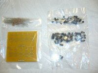
For those that still want the LVC modules, I have made them available now on my RC website. You can find them here: http://www.tppacks.com/products.asp?cat=26. Two 10-cell versions are provided, one that includes the board, all the parts and a detailed set of instructions, and a "deluxe" version that adds two RC-type balancer plugs and a small JST plug for the output. The deluxe kit also includes detailed instructions.

Here's what is included in each kit:

10-Cell%20a123%20LVC%20Circuit%20Basic%20Kit.jpg


10-Cell%20a123%20LVC%20Circuit%20Kit.jpg


The deluxe/complete kit also includes an option for matching male balancer and JST plugs that can be used to wire into existing packs and the controller.

I'm working on finishing up the instructions for the a123 10s4p pack construction kit, and will make these available soon, as well. There will be a version that includes the LVC circuits on the same board that is used to make the balancer connections (as shown earlier in this thread...).

I'm also working on doing a number of kits for the LiFeBatt cells that will at a minimum include the LVC function. If this "clamp" idea pans out, I will probably include this with LiFeBatt boards, and also update the a123-based kits as well.

-- Gary
 
Great work Gary! I'm definitely interested in a version for the LifeBatt cells (12s please!).

Regarding charging: As the extra time/expense needed to add balancer plugs is relatively small compared to the cost of these packs I definitely think it makes sense to add them right from the start. It leaves options open for the future.

The clamp idea sounds good, but what's wrong with an existing solution such as the Astroflight Blinky: http://www.astroflight.com/store/store-type-tem.html?item=products:af-106-123&sid=00011LUvQSjLA74RtU2x0b7
Would this not be able to dump enough current to cope with balancing a pack of more than 1p (2.3 Ah)?
 
brandonh said:
Some RCers already use CC/CV supplies to charge their A123s, and there's even a YouTube video showing how it's done with a Mastech 5020E supply.

I think there's an issue with your overvoltage-threshold-in-series idea. I'll assume that a CC/CV charge is being used, with voltage set to (#batteries*3.6v). In an out-of-balance pack, one cell will need longer to reach full voltage. That lagging cell might be at 3.4v, while the other cells are at the 3.6v target. Since the charger starts in CC mode (not at Vlimit yet), the other cells rise in voltage until the total of their voltages plus the lagging cell voltage equals the charger limit (#batteries*3.6v). At Vlimit, the charger switches to CC mode, with current through the string dropping quickly - many cells won't accept as much current. The cycle stops when all cells have reached at least the 3.6v threshold. But while the lagging cell voltage is rising, the other cells are all being overcharged! The cycle does nothing to balance the pack.

This is the whole reason for the shunt regulator "voltage clamp" design; it enables each cell to rise in voltage to exactly 3.6v, then accept no more current. The pack comes out of every charge cycle balanced.

I probably have as much experience with RC chargers, as anyone on RCGroups, especially as they apply to use with a123 cells, and I can tell you I think you are not right to think that all you have to do is charge a cell until its voltage reaches 3.6V, and then cut it off. The "resting" voltage will end up only being around 3.4V, and it will only be charged to about 80%. What you described is simply a CC charging profile. The whole point of adding the CV mode is so that the cell can be held at that voltage for awhile, while the current gradually reduces down. This is what "tops" off the cell to get it close to 100% charge. BTW, the best voltage to use for this cutoff is 3.65V, not 3.6V. It doesn't really hurt the a123 cells to go over that, to say 3.7 or even 3.8V, but going under won't get you to 100%.

About a year and a half ago, when the a123s first hit the RC world, we did quite a bit of testing with various chargers, and charging profiles. We started simply using regular LiPo modes, which uses a CC/CV cutoff of 4.2V per cell. We monitored the voltage with a PC, as the cells were charged. What happens is that voltage rises steadily at a fairly slow rate until about 3.7V is hit. Then, the rate changes drastically, and it will rise quickly to the 4.2V cutoff, where it stays until the CV portion is finished. We asked a123Systems about this and they said they have done similar tests. They said it doesn't really hurt the cells, but if you did this all the time, it might reduce the cell life. I still have a pack with a number of cells that went through these early torture tests, and it is still going strong with close to 800 cycles on it now and one of my helicopters.

Anyway, the clamp circuit needs to simply limit the max voltage a cell can get to during a charge to 3.7V, and then a normal CC/CV charger can be used, and then you will end up with a balanced pack. :)

-- Gary
 
Thanks for the explanation Gary! That really helps.

I see now, there are three basic ways to charge with balancing:
-charge entire pack in (mostly) CC mode, cut off cells at threshold by dissipating current as heat, as described above
-charge each cell individually with CC/CV chargers
-alternate charging to a simple voltage threshold with balancing (but has issue if one cell is really out of balance and charge never stops)

I guess the next questions are how to dissipate the (3.65v * pack current * # cells) watts, and whether and how you can dissipate that much in or out of a pack. With a perfectly balanced pack, you'd dissipate no heat at all.

How out-of-balance has anyone seen an A123 cell go? This could get us a bound on the time where we'd need to dissipate the heat, and then we'd have some data for the internal/external argument.

Thanks,
Brandon
 
Malcolm said:
Great work Gary! I'm definitely interested in a version for the LifeBatt cells (12s please!).

Regarding charging: As the extra time/expense needed to add balancer plugs is relatively small compared to the cost of these packs I definitely think it makes sense to add them right from the start. It leaves options open for the future.

The clamp idea sounds good, but what's wrong with an existing solution such as the Astroflight Blinky: http://www.astroflight.com/store/store-type-tem.html?item=products:af-106-123&sid=00011LUvQSjLA74RtU2x0b7
Would this not be able to dump enough current to cope with balancing a pack of more than 1p (2.3 Ah)?

Yes, I plan on doing LiFeBatt versions for 6 cells, 8 cells, 10 cells and 12 cell. Maybe 16 cells as well, but it depends on the configuration. I need to see if 16 cells will be easy enough to mount on a typical rack.

The "Blinky", and the Thunder Power 10-Cell TP-210V autobalancer work exactly the same way. They simply look for the cell with the lowest voltage, and try to bring the others down to this level. The problem is the high cells are only discharged at about 150mA, so that's not really going to work here.

-- Gary
 
There's much going on in the marketplace addressing more efficient equipment everywhere. Shave off a watt or two here and there and soon it adds up. Efficiency is becoming more important and it makes sense.

This is why the shunt balancer bothers me. You put energy in and then you bleed it off as waste heat. I think there are better ways.

I just ordered 12 of those single cell chargers that Gary is using. I think charging cells individually may be more efficient than charging enmass and bleeding off to balance. We need to find the clever ways to do it that require fewer parts and simpler designs.

Richard
 
Getting a little obsessive now. Wide awake at four o'clock this morning I came up with another daft idea for balancing cells. But in the clear light of day it doesn't seem so daft.

Am I right in thinking that if I could find a fairly simple and practical way of switching cells in a pack from series to parallel that A123 cells and LifeBatt cells should balance themselves perfectly well without any help?

The idea is to run wires from each cell to a multi-pin socket (possibly two). The cells themselves would not normally be connected to each other. Instead, you have two plugs that fit each socket; one is wired with jumpers to give a parallel (balancing) configuration, and the other wired to give a series (run) configuration. If you fit the parallel plug whenever the pack is not in use you can keep the pack perfectly balanced until you need it.

You also have the option of charging the entire pack as a single parallel string at 3.7V, although I'm not sure how useful that would be.

Granted it's not a very practical idea for A123 cells, but for LifeBatt cells with their screwed terminals it seems workable. For a 12s pack I could use two 12-pin trailer plugs and sockets. As long as I use 10 gauge cable, solder the connections to the sockets and keep the runs as short as possible it shouldn't add too much resistance.
:?:
 
Malcom,

It is a fine idea, IMO. As others have discussed, 10 gauge can be stiff... using double connectors and smaller gauge wire may be easier and provide lower resistance.
 
Back
Top