The care and feeding of a123-based packs...

The power unit is à power switching 48V/400W
(objet n°180206228957 on ebay)
Three résistor 0,2 Ohm /50W in serial is connected for limited start current at 8..10A (if omitted the protection power switching start)
few error is detected on schematic... New schematic is ready and new board is ready (my board is a prototype...)
a Mosfet for protect Pack is add and current is cut automaticly if voltage one cell less 2.3V.
The cost of BMS is approx 100 $ (175 $ with supply power)
No kit for sale... Do it yourself !
 
I work in parallele with Silicium in order to built the full version with 15 cells for a "small" 15S2P battery. :mrgreen:
90% of the job is allready done…
The 15 cells BMS is allready finished, there is some small change in order to accept 56-60V at input in comparison of 12 cells version of silicium
View attachment 1

The 15S2P battery is also rebuilt but still not plug. I must veryfing all links before plug it to BMS.
I have passed a lot of hours to assemble everything. There is something arround 450 components on the board…
And also some couple of hours to verify and test everything !
I hope now, they will be no burning when I will plug the battery ! :roll:
View attachment bat.JPG
 
silicium said:
I do not know if I put my message in the right place...
I make a BMS for a battery A123 (4P12S)...
What do you think of my circuit? (BMS A123 x12 eng.pdf)
Best regards,
Silicium

I'm kind of late finding this thread but I noticed looking at Silicium's schematic that there is a potential problem with the way FINCHARGE is used to shut off Q16, TIP 142.
The input offset voltage of the LM358 can be up to 7mv so even though you've pulled the + input of the LM358 to ground it's possible Q16 will still be flowing up to 70mA of current to the battery stack. You may have already found and addressed this problem, but I bring it up in case you haven't. You may want to find a different way to shut Q16 off.
One other minor point is that for a full 15 cell stack and charging voltages in excess of 50V you have potentials in excess of the voltage rating of the BUZ11. This may not be an issue though since under normal operating conditions the BUZ11 will see the charging voltage - the battery stack voltage.
It's a nice design and a very well laid out schematic. Hope my comments are helpful.
 
Thanks for the feedback !
Schematic is updated... and work fine (tested on 2 board)
for current limit off: Rshunt up to 1 Ohms (current off is <1mA)
all mosfet are RFP70N06 or RFP60N06 Q100 is IRFB4110 (100V, 4.5mOhms)

in sub-circuit for control cell, news components is added for protected ... In prototype, TCM809 is dead...

View attachment BMS A123 x15V5complet.pdfView attachment 1
 
silicium said:
Thanks for the feedback !
Schematic is updated... and work fine (tested on 2 board)
for current limit off: Rshunt up to 1 Ohms (current off is <1mA)
all mosfet are RFP70N06 or RFP60N06 Q100 is IRFB4110 (100V, 4.5mOhms)

in sub-circuit for control cell, news components is added for protected ... In prototype, TCM809 is dead...

View attachment 2View attachment 1

I can see my original comments where a bit out of date, you've gone through a number of revisions since the first schematic I saw. Very nice work. Looks great ;)
A couple thoughts I had, You shut off Q3 when the safety signal is out of range, but you don't seem to shut off Q1. or did I miss something?

On the CELL1 schematic couldn't you connect R20 and R22 to the collector of Q6 and get rid of Q7? or is the gain at Q6 too low and the transition on Q6 too soft?
 
After several cycles, I still have nothing burned...and it's work perfectly.
I have calibrate balancing at 100mA for my small batterie.
A picture with Balancing in progress.
View attachment P1070086_red_2.jpg

I use only for the moment 60v mosfet.
Maximal battery voltage is 54V and charger output is 57V maximal.
Batterie capacity was checked two time. Nominal cells voltage seems to be 3,2V and not 3,3V
Discharging curve at ~5,6A:
décharge_5,6A.GIF

I must focus now on a box
 
Hi Silicium/Snickers,

well impressive BMS/charger, very nice work. 8)

What are the final specs for this? How many watts does it output? How long does it take to charge your packs?

How hard would it be to significantly increase the output power of this design?

So what's next? Any chance of a open design programmable controller? :twisted: :roll:
 
I have plan to charge my 15S2P with less than half a hour with very simple power supply 56V 10A. Today, I use 56V 2,5A with three small adapter in series.

Output power from battery is not limited…for my 15S2P, 100A if you want.You must only add few mosfet in parallel for the battery cutoff when BMS detected one element empty.

My battery link are design to support continuous 50A. The cutoff mosfet 3,5 milliohms 60V extract from one Dewalt BMS will support à continuous 30A with a small heat dissipater. These mosfet from Dewalt BMS are really excellent for this job.

Protection again short cut is performed with a external 30A fuse, a 20A re-armable fuse and the internal battery fuse link already inside Delwalt pack. This is in order to be safe with a battery pack able to deliver 10KW instant power!

100mA balancing takes around 5 minutes at the end of charge. 500mA balancing are possible by added some small copper heat dissipater near balancing transistor. Perhaps I will do if I upgrade my battery to 15S4P version.

About an open design programmable controller, I think Silicium don't have planned to do this. Aim was to propose an affordable design for everybody. There is clearly really more components than one with CPU, but no programming tools are necessary to built it.
 
Snickers said:
...

About an open design programmable controller, I think Silicium don't have planned to do this. Aim was to propose an affordable design for everybody. There is clearly really more components than one with CPU, but no programming tools are necessary to built it. ...

There are good microcontrollers available that only require a USB cable and a PC to program them. The development software is free. A complete development board can be had for $15.

http://moderndevice.com/index.shtml
 
News of my pack 4P12S
Test with 14 Amp discharge:
forum024364_L.jpg

The pack restores 9.1 Ah representing over 98% of the theoretical capacity :D
Well, given all the previous tests, the opposite would have been surprising ...
Now I check that the charger is 'solid' ... Before finishing the integration into the box. If not for news, I retrieved from the original BMS packs dewalt of Mosfets with a RDSon of 3.5 mOhms ... I put 2 in parallel to cut the battery when the BMS indicates an item is empty. The fall of terminal voltage of mosfet at 14A was ... 20mV The fuse was 30A of 55mV drop him!
The total voltage drop (cablage relay + + + mosfet fuse) was 350mV or an equivalent resistance total 0.35/14 = 25 mohm. A 14A I lost 5W = 14x14x25 in the wiring or 1% of the power in charge
 
Nice Work!!!!!!!!!

Love that graph. Super info as I am in the process of putting together a 12cell pack as well. Now I have some data about where to LVC should be.

What type of equipment are you using to put that kind of a continious load on these???
 
About continous load, I use a resistance extract form hair dryer. It's gave me at 48V 265 watts heating .
The most simple solution is to use 3-4 automotive ligh bulb 12v 50-55 watts in serie.
Silicium use something like this.
My battery (box+BMS only=1,35Kg) + 2,4 Kg battery = Total 3,75 Kg 8,3 Lb
Design of box is for 15S4P + some space inside for circuit bracker,...
View attachment P1070106_masse_boite+BMS_red.jpg

I have finished the assembly and I drive now with my 15S2P batterie with BMS from silicium
View attachment Batterie_red2.jpg

First test 4,28Ah+ 0,132Ah (consumption from my 48v Led lighting + controler)
View attachment P1070109_resumé_red.jpg
 
Very nice Silicium, good work :D
 
For those interested...this auction is about 8 hours old... buy it now, $110. He has two, look for the other auction.

http://cgi.ebay.com/36V-DEWALT-BATTERY-DC9360-36-VOLT-BRAND-NEW_W0QQitemZ130198306658QQihZ003QQcategoryZ20794QQssPageNameZWDVWQQrdZ1QQcmdZViewItem

<edit> Sold! This post can be deleted.
 
that's nice work silicium and the battery compartment as well could retire on that alone you would think :D

i am currently trying to construct a dc dc converter based charger( used as single chargers) hopefully with help from doc and gary welcome your input on that thread as well .

but really nice work and its been coming for a long time now and looks tight.
 
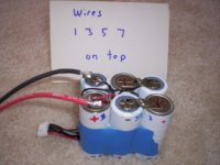
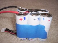
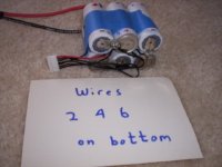
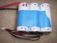
*************** Adding Taps to a 6 cell pack *************************************8

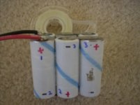
Start with a 6 cell brick
I choose to use the hyperion/polyquest type of tap as that seems the most common.
http://home.comcast.net/~truerc/Charge/chargers.htm
It is the 7 pin balance connector from here (bottom of page on right $4)


File too big error will post pics later
 

Attachments

  • batteryTap2s.JPG
    batteryTap2s.JPG
    23.8 KB · Views: 5,275
  • batteryTap3s.JPG
    batteryTap3s.JPG
    22.7 KB · Views: 5,266
  • batteryTap4s.JPG
    batteryTap4s.JPG
    23.9 KB · Views: 5,267
  • batteryTap5s.JPG
    batteryTap5s.JPG
    21.1 KB · Views: 5,259
  • batteryTap6s.JPG
    batteryTap6s.JPG
    21.9 KB · Views: 5,258
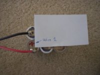
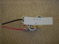
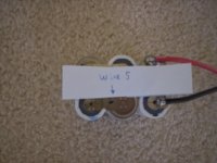
Here it is wire by wire
 

Attachments

  • wire1.JPG
    wire1.JPG
    18.8 KB · Views: 4,633
  • wire2a.JPG
    wire2a.JPG
    17.3 KB · Views: 4,629
  • wire3.JPG
    wire3.JPG
    24.6 KB · Views: 4,623
  • wire3a.JPG
    wire3a.JPG
    21.5 KB · Views: 4,620
  • wire4.JPG
    wire4.JPG
    21.4 KB · Views: 4,621
  • wire4a.JPG
    wire4a.JPG
    14.4 KB · Views: 4,617
  • wire5.JPG
    wire5.JPG
    21.2 KB · Views: 4,614
Wire 7
 

Attachments

  • wire7.JPG
    wire7.JPG
    21 KB · Views: 4,598
So what's wrong with using a lead charger? EG: 10 cells, 36v lead charger, 4.2v/cell. If that's too aggressive an 11 cell battery would get about 3.8v/cell, letting that float a few mins every now & then should balance the pack since they'll quickly drop below 3.6v/cell without the charger.

http://www.slkelectronics.com/DeWalt/index.htm
SLK Electronics said:
On a 3-cell pack, I forced a 130-millivolt imbalance by charging one cell. This is a HUGE imbalance due to the small change in voltage with discharge (per the graph discussed previously). Charging was done using a LiPoDapter at a 6A charge rate. A higher charge rate was chosen because higher charge rates cause normal LiPo cells to become unbalanced. The charge regimen could also have used an Astro 109 Lithium charger. The pack was discharged at a constant 20A to 2.7V. Each successive cycle decreased the imbalance. After several cycles there was still some imbalance but only a fraction of the original.
 
I use one all the time for 4s16p no problems and can't go too high for the unbalance problem.
 
So you're charging the cells with a lead charger, slightly overcharging to balence them?

Are you using a bms? Do you need to periodically re-balance the cells? At what voltage do you charge the cells? Does anyone know to what degree cycle life would be compromised with this approach? Somehow I just don't see tens of thin fragile wires surviving very long in a backpack battery, even less a bms board.
 
Back
Top