Hi everyone,
I recently installed a new controller on my electric motorcycle, but now I'm having an issue with the throttle response. It's extremely sensitive — even a small twist causes sudden acceleration, and it's very hard to maintain a steady speed. When I slightly reduce the throttle, the motor almost completely cuts out instead of decreasing speed smoothly.
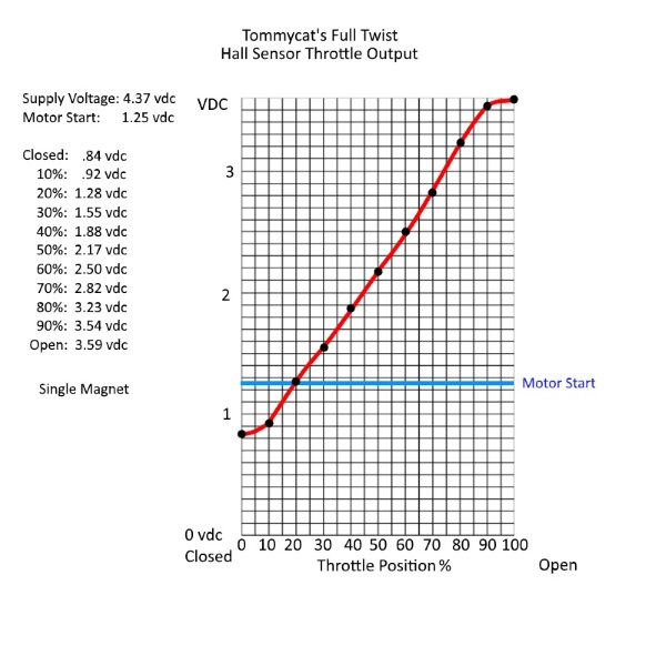
I measured the throttle output:
This makes the throttle feel more like an on/off switch rather than proportional control.
Would adding a buffer op-amp (like LM358) between the throttle and controller help smooth the signal?
Has anyone else experienced this problem after swapping controllers?
Also, I noticed another issue:
When I'm in 3rd gear and go over 65 km/h, if I suddenly release the throttle, the motor creates a strong braking effect — it feels like engine braking or even a sudden regen brake, and the bike lurches forward sharply.
This only happens at high speed — at lower speeds, throttle release is smooth and doesn't cause this behavior.
Thanks in advance!
I recently installed a new controller on my electric motorcycle, but now I'm having an issue with the throttle response. It's extremely sensitive — even a small twist causes sudden acceleration, and it's very hard to maintain a steady speed. When I slightly reduce the throttle, the motor almost completely cuts out instead of decreasing speed smoothly.
I measured the throttle output:
- With the throttle disconnected from the controller and powered externally, the signal ranges from 0.8V (idle) to 4.2V (full throttle).
- But when it's connected to the controller, it only reaches 3.5V at full throttle.
This makes the throttle feel more like an on/off switch rather than proportional control.
Would adding a buffer op-amp (like LM358) between the throttle and controller help smooth the signal?
Has anyone else experienced this problem after swapping controllers?
Also, I noticed another issue:
When I'm in 3rd gear and go over 65 km/h, if I suddenly release the throttle, the motor creates a strong braking effect — it feels like engine braking or even a sudden regen brake, and the bike lurches forward sharply.
This only happens at high speed — at lower speeds, throttle release is smooth and doesn't cause this behavior.
Thanks in advance!