
You are using an out of date browser. It may not display this or other websites correctly.
You should upgrade or use an alternative browser.
You should upgrade or use an alternative browser.
torque sensor for BB ?
- Thread starter curious
- Start date
Beagle123
10 kW
Look at solarbbq (use google). He sells a torque sensor. I don't know what it looks like because he doesn't show a picture. I'd love to know what it is and how to use it.
You mean this:
http://www.users.bigpond.com/solarbbq/torquesensor.htm
From the picture it looks like a custom sprocket is needed, also I do not understand how the wire can be connected if the sprocket turns") .
.
I was thinking about DIY one using either chain tension measurment or piezo sensors mounted on the cranks. The latter would be easy to implement but you have to somehow transmit that information from a moving part to the bike. The former requires some mechanical design which I am not good at.
http://www.users.bigpond.com/solarbbq/torquesensor.htm
From the picture it looks like a custom sprocket is needed, also I do not understand how the wire can be connected if the sprocket turns
.I was thinking about DIY one using either chain tension measurment or piezo sensors mounted on the cranks. The latter would be easy to implement but you have to somehow transmit that information from a moving part to the bike. The former requires some mechanical design which I am not good at.
You might be able to use something that looks like a derailleur that's spring loaded with a strong spring. As the chain tension increases, the spring compresses. Then you attach the guts from a hall effect throttle to the arm so that the throttle increases as the arm is compressed. You could use any small, strong magnet attached to the moving part of the arm and locate the sensor to get the right response.
curious said:The difficulty is that the chain changes it's position so either the roller mechanism should either follow or the roller itself must be flat and wide.
Right. That makes it hard if you need multiple gears on the crank. If you had a single speed up front and located it close to the chain ring, it wouldn't need to change position much.
The only other approaches I can think of get really complicated. Ideally you want to measure the force on the pedals or crank arms, not the chain, since chain tension will change radically with gear selection up front. Without resorting to a strain gauge, the only other way I can think of is to have some kind of spring between the crank spider and the chain rings that would compress as you increase force. The amount of compression would then be measured somehow.
Drunkskunk
100 GW
you could eliminate the problem by having an idler gear that would keep the chain position stable for the sensor.curious said:The difficulty is that the chain changes it's position so either the roller mechanism should either follow or the roller itself must be flat and wide.
The chain would leave the rear cluster moving forward to an idler gear. From that gear, it dips down by a couple inches to a spring loaded idler gear, attached to hall sensors (using an old throttle). from there, it moves back up to the main chain ring. As torque is applied to the pedals, it tries to pull the chain tight, which pulls the second idler gear up, incrasing the output on the sensor.
To eliminate the effect of the chain moving side to side, the axles both idler gears ride on would need to be longer, so the gears could slide side to side by as much as a half inch.
Drunkskunk -
Tension needs to be measured on the upper chain path (lower is unloaded). If I understand correctly your suggestion works on lower path. Also the problem is the horizontal movement of the chain when you change front/rear sprockets.
Tension needs to be measured on the upper chain path (lower is unloaded). If I understand correctly your suggestion works on lower path. Also the problem is the horizontal movement of the chain when you change front/rear sprockets.
I think this part is relatively easy to do. There are flat piezo sensors that can be glued on directly to the crank. If you put two on both sides of the same crank you can then differentially amplify the signal that should minimize the noise. The real problem is how to pass the signal from the moving parts to the frame in a simple and reliable way.fechter said:Without resorting to a strain gauge, the only other way I can think of is to have some kind of spring between the crank spider and the chain rings that would compress as you increase force.
Drunkskunk
100 GW
Yeah, I ment the upper part of the chain, as the chain comes back from the rear gear set, to the front sprocket. the upper path.curious said:Drunkskunk -
Tension needs to be measured on the upper chain path (lower is unloaded). If I understand correctly your suggestion works on lower path. Also the problem is the horizontal movement of the chain when you change front/rear sprockets.
The problem you mentioned about the horizontal movement is accomidated for by having the idler gears able to move side to side on there individual axles..
Attachments
Drunkskunk -
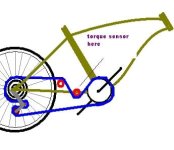
Now I see what you mean. BTW the sensor roller travel can be small enough so the idler roller may not be needed at all. Another idea along the same lines is to have a sensor roller attached to the front derailleur (always have trouble splelling that). This way it does not need to move sideways. The problem with that is that sensor roller mechanism will apply some force to the front derailleur which is not great.
But I still prefer the idea of using piezo sensors to measure crank stress. Just need to figure way to pass the signal from the moving crank to the frame.
Apparently most of these solutions are covered by patents. Although I do not think it is a big deal for a DIY project.
I have not looked at their specific implementation but on the surface I like the Polar idea a lot. In fact it should be possible to measure even static chain tension if one drives the coil with periodic pulse train (say 10 pulses/s) and measure ringing response between the pulses ! All it needs is a U-shaped coil pickup mounted on the chainstay with some protection on top plus some electronics. Adding it to the list of projects to do.
I have not looked at their specific implementation but on the surface I like the Polar idea a lot. In fact it should be possible to measure even static chain tension if one drives the coil with periodic pulse train (say 10 pulses/s) and measure ringing response between the pulses ! All it needs is a U-shaped coil pickup mounted on the chainstay with some protection on top plus some electronics. Adding it to the list of projects to do.
Drunkskunk
100 GW
the problem with the Pizo effect is noise. since the crank is at the foacal point for frame stresses, and since the bike is in constant motion, causing road bumps to shake and stress the whole frame, how do you filter out the tortional stresses and road noise stresses from your actual crank stress?
Since the bike frame is metal, and an excilent condector of sound, there is going to be very little atenuation from the Pizo's standpoint between stresses at the crank, and stresses in the handlebars, no matter where you put the sensors.
To ilistrate this problem a little better, Imagine you take 30 Highly caffinated teenage girls, and lock them in a 10X10 tiled bathroom. Then drop in a spider. Now try to record the sound of only the girl standing in the exact center of the room, from a microphone outside the door.
The sensor isn't the problem, its the CPU and programing needed to do the filtering that would be tricky.
I enjoyed the analogy . I did however make my living working on signal processing and forward error correction in comm. systems for many years so this is not completely hopeless. OTOH I am not very good at mechanical design so the simpler it is mechanically the better.
. I did however make my living working on signal processing and forward error correction in comm. systems for many years so this is not completely hopeless. OTOH I am not very good at mechanical design so the simpler it is mechanically the better.barts
100 µW
but you have to somehow transmit that information from a moving part to the bike.
You could always use wireless; the technology has certainly gotten easy enough. A simple slip ring or battery for power, and put the signal conditioning electronics + transmitter on the crank itself. Beam the signal to the controller (I assume) ... you can get a transmitter & receiver pair for cheap from sparkfun http://www.sparkfun.com/commerce/product_info.php?products_id=7813; they also have simple fm transmitters if you just want analog....
- Bart
If you could transmit power and signal across a moving connection, then you could use bonded strain gauges glued to the crank arms or the shaft somewhere.
Drunkskunk
100 GW
strain guages are realy low current, right? could you power them by inductance? A coil on the crank, and another on the crank's shell?
Yes, the strain gauges are very low power. The amplifier and transmitter would take more power. Some kind of coil on the frame and one on the chain ring would work. I don't know of any off-the-shelf stuff to make the transmitter / receiver.
Drunkskunk
100 GW
I don't think you would need a transmitter or a reciever. if you added a single diode to the crank side, you would have a pulsing DC curcuit for the strain guages. Probably a zeiner diode to also be the voltage regulater. you could then use a second coil closer in on the chain ring to send the signal back.
The signal back would be effected by the speed of course, but a simple compariter could be built to compare the power coil to the reciever coil to filter the diffrence out.
The signal back would be effected by the speed of course, but a simple compariter could be built to compare the power coil to the reciever coil to filter the diffrence out.
Link
1 MW
"MSRP: US $1195"?
Dude! My whole COLLECTION of bikes isn't worth that much!
Dude! My whole COLLECTION of bikes isn't worth that much!
I recall on the old V some guy had rigged a thumb throttle with a derailleur jockey on his chain, using only one chain ring though. Looked pretty iffy but it seems it worked well.
I think it was on this bike (the white FS bike with SLA's duck taped to it) tho it don't seem to be present in that picture.
http://www.endless-sphere.com/forums/viewtopic.php?f=6&t=235&st=0&sk=t&sd=a&start=120
I think it was on this bike (the white FS bike with SLA's duck taped to it) tho it don't seem to be present in that picture.
http://www.endless-sphere.com/forums/viewtopic.php?f=6&t=235&st=0&sk=t&sd=a&start=120
Similar threads
- Replies
- 27
- Views
- 1,892