Trek 3900 RC Build

Nanoha

100 W
Joined
Oct 25, 2009
Messages
171
Location
Sydney Australia
Hello ES, this is my 2nd ebike build but 1st RC build

Many thanks goes to amberwolf and Matt for answering my questions.

Ok, initially my idea was to just get a cyclone 1000w setup to get to work.
My ampedbikes kit + ping 48V20ah was pretty much useless on a 45º hill
so I needed a system that can drive through the gears, but after reading about the RC setups here on ES 1000w just doesn't seem enough >:D

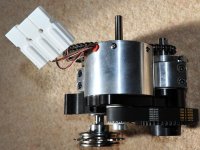
So I decided to go with Matt's 2 stage astro 3210 drive and ordered a lifetech 36v15ah lifepo4.

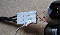
Initially (and still do) I had alot of questions regarding the freewheeling
crank setup and chainring alignment, but that's partially been solved.
It's pretty straightforward when you have all the parts physically in front of you.
 

Attachments

  • MEW_1452.JPG
    MEW_1452.JPG
    63.6 KB · Views: 2,240
  • MEW_1453.JPG
    150.1 KB · Views: 810
  • MEW_1458.JPG
    MEW_1458.JPG
    57.8 KB · Views: 2,240
  • MEW_1466.JPG
    MEW_1466.JPG
    39 KB · Views: 2,240
Those wires look to be hall sensor wires they definitely not your phase wires, no idea where your phase wires are looking at that pic.
...definately don't be connecting your hv160 esc to them anywayz... Matt? what the deal there wheres the mans phase motor wires?
or have Astro severely reduced their specs LoL reckon you could pump a whole 12v 3amp through them before they melt :p

KiM
 
They are the phase wires. If you take a look at the raw phase wires coming out of a lot of RC motors they are often pretty thin - they only look beefier on some motors because they've usually got some heavy gauge silicone wire tails already soldered on to them right at the motor.

Jeremy
 
You gotta be shitting me Jeremy!?!?! They look like servo wires, look at them hanging out of the andersons they look puny!
I will have to have a word to Matt and get some 10ga fitted when i can finally afford an astro i don't like those wires at all sorry
and haven't seen another astro pictured with puny phase wires like that. Looks wrong IMO, not that i know anything when it comes
to electric motors. Long as they are right though wires it up and get it going.... Soz for incorrect info.

I checked all the astro pics i have on Matts drives Jeremy not one has those type of wires muct be a new thing?

All ones i have pictured have thick black wires-->


Two_stage+drive_2.jpg

KiM
 
Kim,

You are hillarious!

Those are huge Andersons. They are not the small ones you are used to. Look at them in relation to the motor size. :)

That is a standard 3210 with normal wires. Part of it is the clear insulation, but most of the issue is the large connectors. It plays tricks with your eyes.

Matt
 
recumpence said:
Kim,

You are hillarious!

Those are huge Andersons. They are not the small ones you are used to. Look at them in relation to the motor size. :)

That is a standard 3210 with normal wires. Part of it is the clear insulation, but most of the issue is the large connectors. It plays tricks with your eyes.

Matt


Yup...they look like 75amp andersons I do use them myself Matt :) I connect my pack to the wring loom with them,
Either way Matt ma main man, You will have to hook me up with some thick black wires like all the other Astros i have pictures of,
.....when i finally get the monies for an Astro of course haha I was going to suggest to nanoha he skimped on the size of the andersons
hehehe... 45amp andersons i hear are the shot? smaller physical size but able to take the higher currents still?

Long as all is good though Nanoha thats the maiin thing... :: makes mental note servo like wires on Astros are good to go:: LoL

KiM
 
LOL AussieJester, I can't stop laughing :D
Servo wires!!!

The wires are pretty thin, thinner than my ampedbikes hub motor's wires. I'm using 75 amp andersons because when I lock my bike somewhere
I intend to take all the electronics + battery with me, and from experience andersons hold up pretty well from frequent disconnects.

Matt, I put the pedal chain on last night and realized that in first gear, the chain is so out of alignment that it would come off the front small sprocket.
On last gear it would probably rub against the drive chain. The solution I've come up with is to actually keep the derailleur working on the 2 inner sprockets
and drive the outer sprocket, but in doing so I'll have to shift the current position of the drive out another 1" or so. I think I might need an aluminium tube the same diameter as my seat tube and mount it parallel to the seat tube. Then clamp the drive to the new post.

If this configuration works then I'll probably get a speed range of 20 - 80km/h :twisted:
 

Attachments

  • MEW_1471.JPG
    MEW_1471.JPG
    27.1 KB · Views: 2,129
Nanoha said:
LOL AussieJester, I can't stop laughing :D
Servo wires!!!

The wires are pretty thin, thinner than my ampedbikes hub motor's wires. I'm using 75 amp andersons because when I lock my bike somewhere
I intend to take all the electronics + battery with me, and from experience andersons hold up pretty well from frequent disconnects.

:p... I have 8ga wires hanging out my Turnigy outrunners so i guess most in comparison look small haha

Yes the andersons are great for that, easy to get a hold of and disconnect...i have only one 75amp on my pack to wiring loom
the rest of my connections i use the gold plated 4mm bullets..

KiM


p.s i download the pic and blew it up they really looked like servo wires, i thought it might of been a "Friday" made motor hahaa...
 
Remember Kim, these are the winding wires coming out of the motor. Your Turnigy has fine stranded wire connected to the winding wires inside the can. These are the winding wires exiting the can. Also, this is a 10 turn motor. The wires are normally thin. This motor is still good for 5kw, though. :)

Matt
 
Christ! Those andersons are bigger than the freaking Astro? LOL
-Mike
 
Yo

I'm with Kim on this one, that just doesn't look right even if it is right? ha ha and I also know how big those Anderson
connectors are as well for scale purposes, also I hope that isn't the discharge lead coming off the battery terminal?
no wait your going to tell me the battery is 4 foot square now and its a matter of scale ;) ;)

Nice set-up though looking forward to seeing it go, perhaps we should start a new thread

"Post pictures of your rigs that don't look right even if it is right! " ha ha, I reckon there will be a few pictures"

Back to the day job

Knoxie
 
LOL no those leads coming out of the battery are the charge leads.
The discharge leads are 6 gauge like the black bundle going to the motor.
 
8) yep glad to hear they are the charge leads 8) was beginning to think my world was turning upside down for a minute :? :lol:

Hey your belts made in the UK? too, watching with interest, liking the battery pack as well.
 
Ok, yesterday I spent 10 hours building, most of the time was spent on making the clamps.
I stood back and admired the bike, laughing at the "quality" of my parts mated with Matt's drive.
Then it was time to switch it on and test it out, I turned the master switch and... pop!
I thought that must have been the extra large spark from charging the extra caps I put in, until smoke started coming from the
rc throttelizer... :shock: I stood there in shock staring at it for awhile before I realized that it's probably a good idea to switch it off!

A quick check and I realized that I reversed the polarity of the ESC!!
At that time, I was too exhausted to even feel anger so off to bed I went hoping I would at least find some humor in my mistake tomorrow.

Today, desperate to get the bike moving, I attached a rx from my rc boat to the esc but I still wouldn't move, realized that the ESC doesn't have
a BEC. No problem, splice a servo connector to the usb port of my netbook and it worked LOL

2.4Ghz tx in one hand and off I went! :twisted:
 

Attachments

  • MEW_1509.jpg
    MEW_1509.jpg
    85.6 KB · Views: 1,999
recumpence said:
Remember Kim, these are the winding wires coming out of the motor. Your Turnigy has fine stranded wire connected to the winding wires inside the can.

Actually my friend, the 8awg in the big HXT motor is because it has 8-turns of ~8awg wire. They are the true coil wires exiting on the big HXT.

What matters with a motor though is the quanity of copper in that slot, if you get there with 1 little strand wrapped a zillion times, or one massive chunk slid into the slot (a 1/2turn motor), the motor is capable of the same power levels, one is just made to operate with more voltage and lower currents, but identical torque/power capability. The Bob the Astro guy knows how to pack that copper in, so I'm sure that motor is just fine. :) The disadvantage of a 10-turn is that it does want quite a bit of voltage to milk it to it's maximum (beyond RC controller voltage), but the huge advantage of a 10-turn is that the controller will live, and find sync very quickly due to the rapidly growing BEMF. If you're going to use an RC controller, and you want something reliable to commute with, it's a pretty wise trade to make IMO.

But! The critical thing that needs to be addressed ASAP is getting that connector from the motor mounted fixed rigidly to something! Everytime a copper wire gets bent/wiggled, it work hardens it a little each time, and the bigger around the wire, the more deformation and hardening happens to the sides of it, soon a crack starts, and failure is soon to follow. Fine stranded wire is not much of an issue because each strand is so small, the stretch/hardening is minimal. On those wires, it's a critical issue to address ASAP.

The bike looks great, and a good solid choice in parts. :)

Best Wishes,
-Luke
 
Thanks Luke, I'll probably zip tie the phase wires to the bike which supports the little "servo wires" :D

Due to the current setbacks, I'm thinking of going sensored but I'm not sure where to get all the parts from eg. halls and controller.
 
Nanoha, I'm fascinated and plan to build similiar to what you've acheived with Matt's engineering.

What's needed now is some performance data. I've struck out in finding info as to what an Astro 3210 can do. Am I reasonable in hoping for a reliable on/off WOT of 15-35mph? Would you ballpark it with a BMC600W @ 48V & 30amp controller; more or less?
 
Remember, a 3210 will peak at 5,000 watts. That motor is capable of pretty much anything a normal bike rider could want. Ypedal runs 50mph continuous on his mountain bike with a 3210. :)

Matt
 
No wonder data is scarce. The motor's not the limiter; a bicyle flying apart is probably the limiter :evil: Haven't heard of the 50mph BMC600S :!: Hmmm, 20-80kph, on 36V, glad to hear that as the HV160 shouldn't be at risk to pop.
 
SoSauty, I've only have limited experience and data relating to my build as I'm still waiting on f@#$^@# USPS to deliver my proper clamps.

At the moment until I get the throttelizer sorted out, I'm stuck to using my RC boat's wireless stick throttle in one hand.

The acceleration in low gear is hurting my shoulders :) On the other hand I have to deal with something screaming between my legs.
 
damn, looks nice god work on that, hope you like riding it :D

i have a question though, what is the pulley reduction ratio, and what is the tooth size and count on the belt? ive got a setup similar in the works now but my belt looks much longer, and is only on 5 teeth of the pinion, so i would be interested to see what your setup is running and if its going to hold up to the 3210. if i could use a shorter belt like yours then my build would be a lot more compact...
 
knoxie said:
Yo

I'm with Kim on this one, that just doesn't look right even if it is right?

hehee glad i am not the only one, at least put some sleeving over themz wires Nanoha preferable 3 or 4 layers or wrap a roll of insulation tape around to make it look like it can handle some herbs damn it! :mrgreen:

Nice work on getting the bike running, is that an EV Logix throttlizer you smoked by accident? have you looked inside it? I'm curious if they all look like a blind folded 5 year old with parkinsons assembled it, mine was nothing short of atrocious, never worked either what a surprise that was after looking inside the box.....Better it failed now than when your 30mile from home i think, besides, the current limiting feature on the throtilizer
does more harm than good when it comes to "protecting" the ESC
it has been reported recently...

Best of luck getting interface sorted, i would recommend Matts servo tester/bec kit.

KiM
 
The reason I want the throttelizer is for it's easy throttle setup and the watt meter (which is still not out).
I don't want to get a Cycle analyst due to the fact that it needs a huge ugly shunt.

I have attached a photo of the destroyed throttelizer, the quality seems decent (if you clean up the charred remains)
Do these no last very long after all?
 

Attachments

  • MEW_1492.jpg
    MEW_1492.jpg
    133.7 KB · Views: 689
Back
Top