What voltage is the light intended to run on? 12v
How much current (amps) does the light take? 1.9amps (23watts/12v, right? this is the light:
Amazon.com )
Ok, well, if your'e still using the same controller as before, it only has 40mA, or 0.040A, available on it's 12v line.
So it cannot run the lights and controller, etc. You'll need a completley separate power supply (DC-DC) that takes your battery voltage and converts it to 12v**** for the lights.
****If the lights are intended for cars, motorcycles, etc., they are actually "automotive 12v" which is really about 13.6-14.4v, so make sure your DC-DC outputs that much, or the lights won't be as bright as they should be.
Also note that light says it has a blue halo. In some places, blue lights are illegal except on emergency vehicles, so you may want to check your local laws about that, or just leave the halo disconnected and unused. The item also has some bad reviews that indicate you're likely to have to take it apart to either rewire it or to physically modify it so that it works as it should.
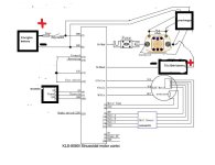
Will this work for the precharger relay (link below): If so, can you help me see the correct wiring with your previous schematic drawing (I've attached it here).
I don't know what the "precharger relay" is intended to do in your circuit. Your diagram appears to completely parallel it with the contactor, so it would electrically be doing the same job, AFAICS. If you intend it to do something different, you'll need to describe in detail the specifics of that, wire by wire and step by step of the process it uses to precharge the controller.
Normally all a precharge system does is put a resistor in series with one of hte battery lines to the controller long enough for the capacitors in the controller to mostly charge up, to reduce current surge into them and prevent arcing of contacts for the main contactor. Often this resistor is placed across the contactor's main contacts, and then when the contactor closes, it shorts across the resistor to allow full main current to be able to flow to the controller.
Some people use a relay or contactor to connect the resistor to the controller (or contactor), and use the keyswitch to turn on the relay/contactor. Some just put it into one of the positions of a multi-position keyswitch (off, start, accessory, on, etc) so when the keyswitch is turned on to the first position, it connects battery positive to the controller thru the precharge resistor. Turning the keyswitch to the next position then turns on the main contactor. Some people just use the old Start button on the handlebars of some motorcycles to do precharge, and *then* turn the keyswitch on after the time they've chosen to wait for precharge to happen.
Note that I also don't see a way for the main contactor to be turned on. It's coil wires go to the box marked Precharger, but without knowing what is going on inside that box, they just "go nowhere". What specifically turns the main contactor on?
If it's coil wires are paralleled with the precharger contactor's coils, the PC can't do it's job because the main contactor has already turned on before it can start doing it.
Without a separate circuit to turn the contactor on, it's either not going to turn on at all, or it's only going to turn on at the same time as the PC (see above).
Regarding the main contactor:
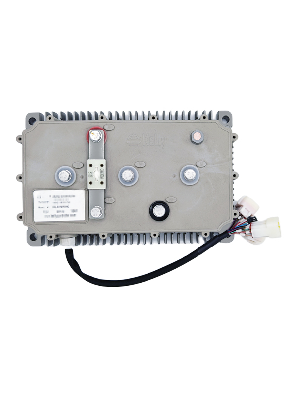
If your controller is still the same one,
Using through-hole MOSFETs. IP66 rated waterproof controller by default.

kellycontroller.com
it can only supply 40mA from the 12v line.
The contactor spec sheet says
Coil Current (nominal at 20°C, 12vdc) 461mA 250mA 122mA
which is a few to several times the current the controller has available on that 12v line, so you'll need to use the external DC-DC to drive the coil.
If the contactor you linked above is intended to be the main contactor, it won't be able to handle the full current your controller may draw, it's only rated for about half of that, AFAICS.
I probably left out details or info; apologies as I was being distracted by JellybeanThePerfectlyNormalSchmoo.


 C36V-96V;Output Voltage