"True Cost" Tributary Thread

fechter said:
A brushless motor can't run without a controller. The controller has a current limiter. The place where the power curve has a dent in it is where the controller is hitting the current limit. To the left of that, the actual current to the motor (torque) starts getting multiplied by the controller as the duty cycle gets reduced by the limiter circuit. This is exactly what we want.

If you look at that Torque curve in the simulation that makes absolutely no sense if the current is limited to a fixed amount. The fact that the torque is INCREASING as you approach zero rpms means that the current must be INCREASING also. It's just simple math, the Torque is the "Power Out" figure multiplied by the Radians per Second number which is related to the rpms. The bottom line is that you normally see a relationship like:

:arrow: Fixed Current * Voltage at RPM = Power Output - Waste Due to Heat, etc...

The Waste component is where the efficiency value comes into view.

An "unrestricted" motor curve is very simple:

1. The Power Curve is a Parabola.
2. Efficiency Curve is a Parabola that is shifted to near the Max RPM's.
3. Amps go from very high to zero as they reach the no load limit.
4. Volts are constant.

With a controller that has a fixed current limit you get:

1. Power curve is a parabola that is "sliced" in half.
2. Efficiency curve is a little more rounded.
3. Amps go from the current limit and then drop afterwards.
4. Volts start low and end at the limit.

That simulation simply baffles me... I'm not sure what to make of it... (it might be very good because it means that they are doing some really "trick" modifications to make stuff happen in cool ways)
 
I'm no expert on this in-depth controller tech...it seems to me when throttle is less than 100%, the controller is acting as a step-down transformer, lowering the average voltage the motor sees while increasing amperage (torque) proportionately.

yes?
 
Yes.
The input (battery) current is limited to a fixed value. As the load on the motor increases and the rpm drops, the limiter decreases the duty cycle. As the duty cycle decreases, the ratio of motor current to battery current increases. The motor gets more current than the battery current due to the controller acting as a buck converter. At low speeds, the motor might be getting 10 times more than the battery current.

You can calculate the motor current roughly by knowing the duty cycle, the battery current, and the efficiency of the controller. The controller efficiency is usually quite high.
 
Take a look over at the newly created "User Friendly" Motor Physics thread. What's freaking me out with this simulation is the "bulge" the is showing up to the left of the power peak. That's NOT supposed to be there in a typical ontroller and I don't know what they are doing to justify the "35 Amp limit" rating when they obviously have to pull more amps down low in order to get torque figures like that.

Something is wrong or unexplained to my satisfaction at this point...
 
Safe fechter just explained what is going on. Google "buck converter" have a look at a simple schematic. The fet and diode would be your motor controller, the inductor is your motor. Your average slap a motor to a controller doesnt make for a very nice buck converter but it still has the same effect.
Joe
 
"Fixed Current" for a controller means "fixed current".

If the battery has a current potential of 100+ amps and the "fixed current" limit of the controller is 35 Amps (a realistic scenario) then the power output is defined by:

Volts (at a given rpm) * Amps (capped at 35 Amps) - Losses = Power Output

But someone "might" try to use the "Power Input" figure instead of the output one and simply overlook the losses.

And guess what? That appears to be what they did on the Simulation. Here's a quick chart that I ran off of my spreadsheet comparing the "After" torque curve (the real one) verses the one that you get from the amount of current to PUT INTO the system "before" losses. At low rpms you are trying to walk in the equivalent of quicksand!
 

Attachments

  • torque before and after losses.gif
    torque before and after losses.gif
    5 KB · Views: 3,318
No, i was talking about the input and output of the motor controller, not the motor itself. What you saw is a normal artifact of the motor controller checking the input current and not the output. It is normal, its not to be worried about, dont think too hard about it.
Joe
 
But do you agree with my point which is that when it comes to the "real world" of how much torque actually hits the pavement through the rear wheel that you would never get torque numbers like in that Simulation with a "fixed" current controller?

:arrow: They are using energy figures to get torque "before losses" so the "actual torque" verses the "torque potential" will be very different. The "missing torque" is expended in the form of heat in the motor and in friction. It's what the "How To Blow Up Your Motor" topic is all about... losses produce heat and subtract from torque and power. (it creates inefficiencies in the system)

Do you agree or disagree? If you agree then we've come to the end of this mystery... otherwise I'm not getting what tangent you are taking.
 
I seem to be failing in my explaination

A controller can be designed to have either a limited input current or a limited output current. They are not the same. Most controllers have a constant INPUT current limit. At high loads, when you hit the limit, the output current will be much greater than the input current, resulting in increased torque (at reduced speed / voltage).

So for a controller that limits based on INPUT current, the torque graph will rise on the left side, not stay flat. If the controller limits based on OUTPUT current, the torque will be flat once you hit the limit.


safe said:
"Fixed Current" for a controller means "fixed current".

If the battery has a current potential of 100+ amps and the "fixed current" limit of the controller is 35 Amps (a realistic scenario) then the power output is defined by:

Volts (at a given rpm) * Amps (capped at 35 Amps) - Losses = Power Output

But someone "might" try to use the "Power Input" figure instead of the output one and simply overlook the losses.

And guess what? That appears to be what they did on the Simulation. Here's a quick chart that I ran off of my spreadsheet comparing the "After" torque curve (the real one) verses the one that you get from the amount of current to PUT INTO the system "before" losses. At low rpms you are trying to walk in the equivalent of quiksand!
 
fechter said:
A controller can be designed to have either a constant input current or a constant output current. They are not the same. Most controllers have a constant input current limit. At high loads, when you hit the limit, the output current will be greater than the input current, resulting in increased torque (at reduced speed / voltage).

Let's do some numbers:

Normally a 35 Amp controller limits the "input" current into the motor to a maximum of 35 Amps.

This alternative controller could watch the "output" side of the motor (after the losses have already taken place) and set the "output" side to 35 Amps. (and I know that there's some backwards logic that takes place to do it) But this means that the "input" side is actually going to be allowed to rise to a level like 50 Amps (or more) as you approach zero rpms.

Does this really qualify as a "fixed current" controller if it behaves like this? What about things like current draw limitations for Lithium? Without an additional circuit breaker you could blow up your batteries by accident thinking that you were okay.

Is this an "established fact" that there are controllers that work this way and is that controller in the Simulation one of them?
 
And let me add on top of this that an "output current based controller" comes very close to being the perfect idea because you are allowing more power into areas that normally have none. It's ideal for a hub motor because you can't add gearing and being in a situation where you are at low rpms and need power you literally need to burn some energy in the form of waste to get anywhere. (it's a sacrifice of energy that is worth it for a hub motor)

Peak efficiency is all about high rpms. (and unaffected by this controller)

Low end torque could really be helped with this "backwards" controller idea... :wink:
 
Im not following your naming of the "output based" and "input based" controllers. The controller that your having problems with, i would call an input based controller in that it is limiting the current going into the controller no more no less. I hope that you agree with me that a controller should be as efficient as possible. Now in order to limit the current demanded by the motor and thus the current drawn into the motor it must limit the output voltage. Also at the same time lets acknowledge a fixed input current at a fixed input voltage equals a fixed input power. So following conservation of energy if the output voltage drops the output current must go up.
I am almost under the impression that when you say input based and output based that you are talking about the positive and negative leads of the motor. The reason for this is that you mention an "alternative controller that watches the output side of the motor (after the losses have already taken place)" well you can only drop voltage in a circuit current stays the same in any given leg of a circuit and well current going into the positive side of the motor is the same as the current coming out of it. I know your good at the math side of electronics im not sure if you know the ins and outs of electronics if what i said above is a simple typo on your part then fair enough i do the same, if not it shows a serious misunderstanding on the basic behavior of electricity and your due for some studying.
Joe
 
I was trying to imagine just how a controller could produce those numbers. You have to understand I'm the SKEPTIC of those Simulation results. I'm simply offering possible theories about what "strange" behavior is going on. (it does sound pretty far fetched if you think about it)

If a controller is "fixed" in it's current limit then a 35 Amp controller will not let any more current through at 100 rpm as it does at 2000 rpm. The maximum "should" always be 35 Amps. (volts can go up or down but the "current" is limited)

So I'm simply saying:

"What the heck is going on in that Simulation chart?"

(it doesn't match what is "normal")

The most plausible explanation is a simple error where they calculated torque using "Power Input" and not "Power Output". Torque is a physical thing of motion... it's "what hits the road" that count's not the heat you waste inside the motor... (they are counting motor heat as part of their torque value it seems)

If you read their disclaimer it's pretty clear that other people spotted the error (and complained most likely) and they confess to the chart being off by 20% or more. That 20% error is about what the heat losses would amount to. So they seem to know of the problem but for whatever reasons don't want to fix it...
 
I dont really see why your stuck on that its limiting the current going into the motor. There are two methods to limiting current in a motor controller either the input current that is going into the controller or the output current that is coming out of the controller. If the current going into the controller is constant than the output current can and will vary and cause the rise in torque that you are concerned with. In the same breath if the output current is constant than you would have a varying input current, and im sure if you watched the input current of such a controller on a graph you would be just as perplexed. It is simply something that controllers do the input current going into the controller coming from the battery and output current coming out of the controller and going to the motor are not the same.
I suggest that you look up dc-dc converters, switch mode power supplys, and inductance. If you do this you will have a sound base for understanding what is going on here.
Joe
 
How about this...

Could you make up a spreadsheet and place the values for this controller type into it and post it here?

I've got the formulas for the "regular" type and it would be good to see side by side how the two controllers operate. I'd like to see the formulas for this other controller... I'm going to post the "regular" one's in a minute...
 
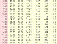
Okay, first we have an "Unrestricted" 750 Watt 36 Volt motor:
 

Attachments

  • unrestricted 04.gif
    unrestricted 04.gif
    12.1 KB · Views: 3,243
  • unrestricted 03.gif
    unrestricted 03.gif
    12.2 KB · Views: 3,243
  • unrestricted 02.gif
    unrestricted 02.gif
    12.2 KB · Views: 3,243
  • unrestricted 01.gif
    unrestricted 01.gif
    11 KB · Views: 3,243
Okay, now we have that same motor with a 40 Amp current limit on the controller:

(if there are as of yet some "unknown" physical properties going on I would really like to learn what they are. If this isn't a "mistake" then I want to know what is happening and how it affects my spreadsheet values)

These values should all seem "normal" if you glance through them.

Torque is found in a formula that goes:

Torque = P(out) / (RPM * Constant)
 

Attachments

  • 40 amp 04.gif
    40 amp 04.gif
    12.2 KB · Views: 3,248
  • 40 amp 03.gif
    40 amp 03.gif
    11.7 KB · Views: 3,248
  • 40 amp 02.gif
    40 amp 02.gif
    11.3 KB · Views: 3,247
  • 40 amp 01.gif
    40 amp 01.gif
    10.5 KB · Views: 3,247
Okay, I wrote to "ebikes" and they just got back to me on a question about the Simulation:

"You would be correct if the current limit referred to the motor current.
However, in the crystalyte and most other chinese controllers it is the
input (ie battery) current that is regulated. At zero speed the motor
current can be substantially higher than the battery current. This is
born by experience as well, as you most certainly do get more torque at
lower speeds while an ammeter always reads "20A" from the pack."


The sentence:

"At zero speed the motor current can be substantially higher than the battery current."

...baffles me. Is the current the same everywhere in a circuit (like through a motor) or is the current different at different places along the circuit? How can the current be limited to 35 Amps at the battery and then be 50 amps at the motor?

Have I missed some basic physical property of electricity here?


(and if so what can I do to correct the formulas?)
 
fechter said:
A controller can be designed to have either a limited input current or a limited output current. They are not the same. Most controllers have a constant INPUT current limit. At high loads, when you hit the limit, the output current will be much greater than the input current, resulting in increased torque (at reduced speed / voltage).

So for a controller that limits based on INPUT current, the torque graph will rise on the left side, not stay flat. If the controller limits based on OUTPUT current, the torque will be flat once you hit the limit.

This seems to answer the question in the same way as "ebikes" did. I simply "don't get" this other type of controller. Oh well, maybe if I sleep on it it will start to make sense... :wink:
 
I believe its due to the brushless motor pulsing. Pulse width modulation as they call it. Fetcher told me once that even though the current is only 20 amps at batteries, its always double at the brushless motor.
 
D-Man said:
I believe its due to the brushless motor pulsing. Pulse width modulation as they call it. Fetcher told me once that even though the current is only 20 amps at batteries, its always double at the brushless motor.

Well, given the relationship of electricity and energy in/energy out, that would be saying to keep the amps higher, you sacrifice from something else like voltage. So If you start with 48 volts @ 20 amps, you can push out more amps if you take away some of the voltage. So if the controller is trying to "push" the motor harder, it would push more amps but at a lower voltage. Since voltage more or less regulates the speed, at lower speeds, lower voltage makes sense. Kind of like a slow moving river can push a car down it better than a fast moving little creek can.
 
D-Man said:
I believe its due to the brushless motor pulsing. Pulse width modulation as they call it. Fetcher told me once that even though the current is only 20 amps at batteries, its always double at the brushless motor.

I think you're right. This is an effect that the PWM creates. This is from the wikipedia website:

In a circuit known as a chopper, the average voltage applied to the motor is varied by switching the supply voltage very rapidly. As the "on" to "off" ratio is varied to alter the average applied voltage, the speed of the motor varies. The percentage "on" time multiplied by the supply voltage gives the average voltage applied to the motor. Therefore, with a 100 V supply and a 25% "on" time, the average voltage at the motor will be 25 V. During the "off" time, the armature's inductance causes the current to continue flowing through a diode called a "flywheel diode", in parallel with the motor. At this point in the cycle, the supply current will be zero, and therefore the average motor current will always be higher than the supply current unless the percentage "on" time is 100%. At 100% "on" time, the supply and motor current are equal. The rapid switching wastes less energy than series resistors. This method is also called pulse width modulation, or PWM, and is often controlled by a microprocessor.

So I will have to factor this in somehow in order to adjust for the "warping effect" that the PWM controller causes. I might just be on the verge of comprehending this strange stuff... :wink:

Next question:

How can we figure this "warping effect" in practice?

Is it a linear relationship?

50% duty cycle = 50% current amplification?
 
Well im glad that your starting to understand now even though for some reason D-man saying it is what made you believe me. But for your question.

Ideally it should be linear but it doesnt have to be. If the inductance of the motor is too low for the switching frequency than inductor current will hit 0 at lower duty cycles and your calculations will be off. If the inductance is great enough for the switching speed than it will be a linear relationship, its a good enough assumption to make with a regular axial can motor with a real coil, take a perm motor or an etek which have a very low inductance than i wouldn't bet on it.

Joe
 
Well so far I did the most obvious thing and took the relative duty cycle as a percentage and then multiplied it by the torque and "sure enough" bingo that "warp effect" produced the curve that was in the Simulation.

Another question is:

What does this effect apply to?

Is it strictly something that applies to Torque?

I tried associating it with Power Output, but then it throws the efficiency curve all out of whack.

The net effect is pretty small over most of the powerband, but down really low the effect definitely shows up.

But the "moral of the story" (for me anyway) is that ALL motors have this "warp" when they use PWM controllers. So my original inqury about hub motors is still unresolved because I'm still not sure how "real" this effect is and if it means that I can really go without gearing. (which is definitely giving me the wide torque options)

All this "extra" torque shows up in the worst place from an efficiency standpoint so if I relied on the effect to climb hills I might be getting myself into trouble...
 
OK, I think it's starting to sink in now...

If there were no losses, then around 50% duty cycle would double the current.
100% duty cycle (full on) input current = output current.

Likewise, you might get 3 or 4 times more current at lower duty cycles.
This would be like starting out on a hill with full throttle. There's definitely a limit to how much "current amplification" you can get, but I'm not sure what the practical limits are.

I don't think it's a linear relationship in real life. Unfortunately, there are all kinds of losses, and worse yet, some of them are non-linear and hard to predict.

If you're running an Etek, the inductance is very low, so the switching frequency needs to be much higher to avoid saturation. If properly dialed in, the efficiency should be very high.

You could possibly model based on a switching power supply.
It works just like a switching (buck converter) power supply, except the motor windings are acting as the inductor. Under load, these windings might not behave like ideal inductors (understatement). In fact, they can become very lossy if they are not near their optimum frequency. The iron in the armature (or stator in a brushless), is not usually good at high frequencies.

Another sort of bad thing is the high current spike that happens during flyback. Since copper losses are I2R, having a peak that's higher than the average will cause more resistive losses.

All the losses in the controller should be small compared to the other losses, so don't lose sleep over them.
 
Back
Top