using ex hoverboard brushless motor wheels

chuffer

1 mW
Joined
Aug 18, 2024
Messages
10
Location
south wales (UK)
I would appreciate some help please.

I have a standard mid size mobility scooter but it’s size makes it not suitable for visits to restaurants, theatres and the like, due to the problems of where to leave it safely.

I want to convert a 4 wheeled knee walker, a type of mobility aid for those with a damaged knee and is a replacement for crutches, into a low speed ride on.

I thought I would buy a used hoverboard with brushless motors fit and connect up one or both wheels.

I can manage the mechanical and wiring OK but identifying a brushless controller is out of my reach.

New SWAGTRON T1/T3 6.5″ WHEEL / MOTOR 2″ AXLE – 36V, 250WATT can be bought new for around £20.00 each.

Having not bought a used hover board I can’t say what the motor might be but I believe are also all 36 volt.

My scooter ( brushed motor ) now uses 24 volt Lithium batteries in an easy portable bag which I would want to make use of.

The fastest I would ever need to go would be a slow/medium walking pace and would be generally on level ground.

Any pointers would be wonderful.

 
I’d start by looking at what already exists and use that as reference to your project. I searched “electric walker” and found this. It looks like it’s using those same hoverboard motors. This model also uses a 24v battery. You would only need to source a 24v brushless controller (or 2, one for each motor) to connect everything. You can even use your existing battery, given it’s got the amp output you need.

The hardest part may be mounting all the hardware. I’ve used Sendcutsend.com for custom brackets to mount a motor. I used a template that they already had, but you can create your own CAD file and have them machine that part to EXACT dimensions of your project.
 
What are the laws regarding providing accommodations to those who require this type of assistance? Dimensions, etc. or other parameters?
 
This seems like less of a motor and mechanical problem to solve, and more of a control system problem to solve. How do you propose to throttle the motors? How do you propose to steer it? Is this thing going to require both hands to operate (throttle, brake, steer)?

Most of the people I know who tried a knee scooter to recover from injury or surgery weren't able to get along with it, and resorted to crutches or canes instead. Clearly some folks can make a go of using these things, but I do wonder whether motor power is actually a desirable advantage.

The smaller sorts of powerchairs have addressed the same issues. Maybe you can rent one, if your knee situation isn't permanent.
 
Thanks for the replies.

I hope the links work OK

The electric walker is way to big.

Remember, I already have a mid size mobility scooter which is quite big and therefore the restaurant etc with the where to leave it problem and I do have the occasional bus ride to where parking is an issue.
.
I already have the knee scooter which is less than half the size and changing the knee rest for a seat is very straight forward, has all the steering and braking in place. example Knee Walker Knee Rover Knee Scooter | eBay

As Chalo correctly says "just a control system problem ( thank's Chalo )

Fitting speed control is easy enough, just a case of mounting a potentiometer with a method of release causes it to zero, also not a major problem. ( slot car controller )

The wheel +motor is also easy and mounting them will not be a big issue for me. SWAGTRON T1/T3 6.5″ WHEEL / MOTOR 2″ AXLE – 36V, 250WATT | eBay

The big question is identifying the correct brushless controller to wheel motor.

Some advertised have far to many connectors to just control the speed under manual control.

Might this be all I need Brushless Motor Speed Controller Switch CW CCW Reversible DC 5V-36V 15A 3-Phase | eBay will it drive any/all wheel brushless motors ???

What more do I need to know to make the match ?

What does "CW CCW Reversible" mean, I do not need to reverse but it would be a useful addition, and what are the

MC MB and MA connectors for ?

I have looked for guides for brushless motor control without success, any pointers to one/any ?.
Clock Wise and Counter Clock Wise, MA,B,C will be the 3 phase wire connections.. ( the Blue Yellow and Green thick wires in the swagtron motor pics) you will probably have to experiment for the correct sequence.. you may find an ordinal sequence of B,Y,G indicating the abc order to connect in the motors docs? but trial and error until the motor 'runs smoothly' is a common solution..
Your probably better off looking at more expensive and configurable ebike controllers so you can configure power and speed limits into the system f/w, and tune the vehicles responses to control input for a smooth ride. a 15a kt controller and lcd display will cost circa $80-100 but then you can use an off the shelf speed controller twistgrip or trigger..
 
This is one of those a “A little knowledge is a dangerous thing” situations.

Fill.

Thanks for your comments, the problem is that this started as a reasonably cheap solution to anything available on the market which usually has a price tag starting at 4 figures and in fact turns out is not available !. ( in the small size, a very important consideration )

I have now found a couple of “Guides to brushless motors for dummies” so have a much clearer understanding.

The thought of having to program a controller is not out of the question but does seem an overkill for my simple needs of always low speed on 99% level ground and generally 300/400 meters distances.

Reading and looking at some hoverboard wheels, they appear to show the 3 phase wires and in some cases 8 other wires, which I assume is the sensors in relation to knowing the motors position before starting, load feedback, and braking etc ?.

The controller Brushless Motor Speed Controller Switch CW CCW Reversible DC 5V-36V 15A 3-Phase | eBay clearly only has the bare supply requirements but adding an additional pot to the speed control circuit should allow the supplied pot to set the max speed and the other, in some kind of thumb or trigger to stop, start and the crawl along and of course a kill switch.

Can’t fit a standard throttle control as It’s fitted with two locking brake levers into one cable.

My question now is………. Would the above controller and the ABC connectors only make the motor run, providing of course I got the sequence correct ?.

If so, I could experiment from there including with my local cycle shop and they might get me down to one cable.


My question now is………. Would the above controller and the ABC connectors only make the motor run, providing of course I got the sequence correct ?.

Yes. the wrong sequence, might move the motor a little bit and make it buzz..
Next you may learn about square and sine wave controllers, the above bein a square wave controller imho
so even with dual pot speed control power on/off could be sharp and jerky- tho i could be wrong ? however i suspect a gentle and smooth pull away and slow to stop would be appreciated.

Brake cut offs aka emergency cut offs are a good thing and would be VERY beneficial. an unexpected/unwanted surge from a bldc can be VERY un-nerving and dangerous
 
Fill.

Thanks again for the pointers.

I do know about square and sine waves, never gave it a thought re motor control being up to now a DC man, I assume the sine applies the power smoothly ?
Found sine wave bike controllers like 36V/48V 350W Brushless DC Motor Speed Controller For Electric Scooter Sine Wave | eBay
Lots more connectors for some very classy features which I could probably ignore most, though I might work on the braking ?.
The, bigger question now is again identifying as none seem to be supplied with any kind of manual.
Found on the site How to Determine the Wiring for a Brushless Motor
Which looks ( without yet having to hand the controller and wheels ) very useful.
I’m still thinking of buying a used hoverboard, to get two wheels, and only intended to power one and might get some useful mounting bits from the chassis.
Also found advertised other useful bits like thumb and twist throttles.

Work in progress…………
 
I am currently recovering from a broken heel bone and out of boredom I designed a drive system to motorize my knee rover scooter. I have not tested it yet. I designed it to use the motor and cheap #25 chain from a razor E100 scooter I found in the scrap bin. The motor is a simple brushed MY6812B motor you can get from amazon for $40usd. A simple brushed controller with reverse from amazon is about $20.

Maybe you can get some inspiration from my experiments thus far. I only have 3 weeks left with this cast so if you like my idea maybe I can just send you my parts. The motor mount plate is pretty specific to the KneeRover brand scooter but It might be a good starting point. Most of these knee scooters look the same anyway.

Like you, I began my brainstorming with hoverboard motors I had on hand. The problem is that the wheels on the scooter have to be all the same size. It only works when the steerer tube is perfectly vertical. Any rake in the front end would make the scooter very unstable.

Next I moved onto the idea of just cutting my electric skateboard in half and putting it on a hinge such that when I stand on it with the good foot it friction drives the scooter wheel. In rough preliminary testing it did have enough power to move the scooter but the skateboard hub motors are really optimized for higher speed than I wanted for the scooter. The upside to using the electric skateboard is that it is a complete vehicle with all the parts ready to go in a compact package.

boarddumb2.jpg

I finally settled on this design with the Razor scooter motor. There are 2 plates that clamp to the wheel and drive from the 10 bolts that fit tightly in the corners of the 5 wheel spokes. The sprocket mounts to those drive plates. A replacement wheel is $17 so if it is too much torque its not a huge problem.

With a 7s 28v battery and an 80tooth sprocket it should top out at around 8mph which is plenty on a knee scooter.

I made all the parts from aluminum and the whole thing probably adds 8lbs to the scooter. I also don't like the fact that the motor is engaged all the time which will add drag when when maneuvering in tight quarters without power. With my injury I dont have access to my normal CNC machines so a drive coupler for a selectable neutral mode was just not practical. This whole system was cut on a waterjet from flat plate.

Image 3.jpg

Image 4.jpg
Image 5.jpg

Hopefully I will get a chance to test it out and report back. The parts are all made and just need to be mounted. It's just a race against time. The longer I procrastinate the closer I get to not needing this which is incentive to just return the $30 in chain and sprocket I bought for it.

Good luck to you.
 
Here is a complete set with tooth / sprocket to make something: https://nl.aliexpress.com/item/1005003624638424.html

And this is a wheelbarrow motor; https://nl.aliexpress.com/item/1005006543439232.html

Make sure you know now much Amp Max Continuous Discharge your 24v battery is rated for.
Make sure you know which protections your battery has built in. Because many times those protections are in the controller and not in the battery.

Hooking up your battery to another controller that pulls more amps then the battery is rated for can result in fire.

Even if you would use a hoverboard motor with a hoverboard battery and use an out of spec controller you can risk fire.

What you could do is get a used ebike and use that complete system. Take out the hub motor and make that 'friction drive' to you wheel.
 
Thanks Bob for the pointers.

I have paid attention to controller specs, battery loading etc but it's always good to get a reminder'

Too many fires of electric scooter charging unattended.

I'm well on my way with the project, put back because the carrier lost the sine wave controller so a reorder was needed.

Got the hover board two wheeled motors mounted to the knee walker, controller tested, got the hall and rotation direction wiring sorted.

Found a great manual for "connecting brushless DC motors to DC controllers" on Pittman site.

Have not investigated reversing, probably not issue to push back a bit with your feet, the steering lock ( turning circle ) is very good.

Waiting for the thumb throttle/kill switch to arrive and next will a ride on test.

I might even invest in a saddle with a back rest !

It will then be down to getting all the electrics boxed up and then, away to go...................

Every time I have looked at Aliexpress the carriage has been horrific, in this case £65 for the product and £86.00 carriage.
 
Some more help please.
sine wave brushless motor's controller.

During construction testing I have been using a 10k pot as a speed regulator which needs to be a third of the way before the wheel turned and under load the speed is a bit variable without being adjusted.

Bought a thumb throttle controller and was surprised I could not measure its resistance leading me to believe it is digital unit.

The questions are..........

Are all bike speed controllers digital.
Have I just been luckily using a resistive device on a digital controller that worked
The wiring is a colour match, would I damage either if I gave it a try.

Thanks
 
The questions are..........

Are all bike speed controllers digital.

Generally speaking, most Ebike controller throttles fall into two categories.
Hall sensored throttles which I would think you refer to when saying "digital". Electronic may be a bit more accurate, as they put out a "linear" signal output. And is an integrated circuit, with a few other electronic parts included besides the actual hall sensor itself.

MnBwIcO.jpg


And potentiometer type throttles, such as what you had used.

For more detailed information on these two types of throttles, see this thread...
Guide to Hall Sensor Throttle operation, testing, and modification. - Electricbike.com Ebike Forum

As always, there are exceptions... An Arduino programmed signal PWM output for one.

Have I just been luckily using a resistive device on a digital controller that worked

As each type of throttle, outputs a different signal voltage level, this would seem to be true.
Depending on the controller, it may require one type or the other. Or may be programmable to except either, or a specific throttle signal input voltage.

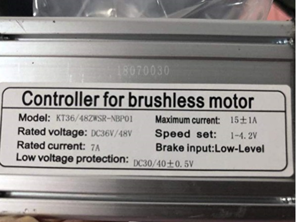
Example of a hall sensor throttle controller expecting 1-4.2V "Speed Set"...

UnqT5Mq.jpg


The wiring is a colour match, would I damage either if I gave it a try.
I would say to NEVER depend on wire colors solely.
Not unless specifically identified by the throttle/controller supplier.

See the throttle thread above on how to verify.

The main threat would be to accidently short the 5vdc regulated controller power to ground. :mad:


During construction testing I have been using a 10k pot as a speed regulator which needs to be a third of the way before the wheel turned and under load the speed is a bit variable without being adjusted.

This thread discusses obstacles that may be run across with different throttle signal voltage inputs, and the controller's responses to them.
Using an On/Off-Momentary Push Button Switch that’s normally open to replace a hall throttle.

It's the variable speed with no change of input that sounds problematic to me...

Hopefully this will give you a bit to chew on and keep you out of trouble. Any questions or uncertainty please ask, BEFORE you experiment. :)


Regards,
T.C.
 
Tommycat, you are a star !

Thanks for a very clear steer, the Guide to Hall Sensor Throttle operation, testing, and modification.
i
s excellent and I hope over the next week or so to apply it and identify my controller and thumb throttle and will report back of the outcome.

I only need walking speed so the information to set the start and wot will provide that.

It's a long story but, I ended up with a low cost controller with no marked connecters or map and was lucky that the hall and motor power leads not only were the same colours but the same connectors and took a chance using guidance from a Pitman post.

I was able to measure the speed connector to determine which way. ( the only three pin socket )

So, I have many connectors that I don't need ( or understand ) but it would be good the get a key switch to power it off against disconnecting the battery, there are a pair of single white wires that are plugged together that looked a likely candidate but disconnecting it did not result in a power down.

I am very mindful of your warning about the lost of sensor ground results in full throttle so may have to exchange my brake lever for one with a kill switch wired in to the 5v throttle supply line.

Thanks again.
Regards
chuffer

BTW. FYI.
My controller Speed sets are 1.2 to 4.4

 
Glad to help! Thank you for your kind words, much appreciated. :)

So, I have many connectors that I don't need ( or understand ) but it would be good the get a key switch to power it off against disconnecting the battery, there are a pair of single white wires that are plugged together that looked a likely candidate but disconnecting it did not result in a power down.
As regards to an On/Off power switch circuit…

Links to the following parts that you are working with?
Controller (hall sensor throttle use confirmed) ;)
Motor
Battery

Typically I would look at two single wires that connect to each other as ether a “learning” or “speed limiting” circuit, to name a couple possibilities.
From your description, look to see if you notice a difference in power output when disconnected or not. (Speed limiting.)
 
TC.

If you were asking me to identify the parts I'm using...........

Motor's = (2) are from a Hoverboard, 36 volt by I think 15amp/250 Watts. (the watts not labelled, but I got it from somewhere )
Battery/s = 24volt >20 amp( 2x12 lithium or lead acid, I have both ) used in my mobility scooter.

The use of 24 volts successfully reduced the top speeds. but do need to be reduced more ( work in progress )

Is a kill switch wired in to the 5v throttle supply line the correct place ?

Thanks
 
If you were asking me to identify the parts I'm using...
Yes, in regards of finding the best solution for a total power off. I.E. No battery current being used by the system.
What controller did you get? Link/Sticker picture…


Is a kill switch wired in to the 5v throttle supply line the correct place ?
Depends on what you are wanting to do?

This was a recommendation for throttle modders that may be trying several different types of hacks so to speak. So that they could be safely tested, with an easy disconnect available. And to reduce accidental starts.

If you’re careful and knowledgeable of possible problems, which it sounds like you are. I wouldn’t press you to do this unless you desired it.

Lastly, this would not totally work in the place of a battery disconnect. As I think some battery current would still be used by the controller being in stand by.

I would encourage you to install break switches that would hook up to the controllers low brake circuit. Which would automatically stop the controllers power output and deactivate the throttle when actuated, and held down. A nice automatic fail-safe especially if you let someone else use your scooter.
But again, with your systems relatively low power output, it would be for you to decide.
 
TC

The long story I avoided telling on the 18th is that the controller I ordered had all the wires labelled but was lost by the carrier and I asked the supplier if he had another to which he replied yes so I bought another for delivery the next day and paid extra for that..

When it arrived it turned out to not be the same, unlabelled and was dated made in 2014, I was able easily to identify the four I needed and was keen to got on so I kept it.

I spent a long time trying to find other suppliers with IT that I might get all the labels without success..

I don't blame the supplier as he would not be aware of my desire for labels and he was very apologetic over the lost item and chased the carrier repeatedly until they acknowledged it's loss and split with me the extra cost of the overnight delivery.

I suppose I could buy another of my first choice from another supplier and change the hall connector ? Pardon our interruption...

"Lastly, this would not totally work in the place of a battery disconnect.
As I think some battery current would still be used by the controller being in stand by."

With speed control at zero it pulls 250Ma. but I did not dis the 5volt line.
 
Sorry to hear of your shipping troubles and glad you got a reasonable resolution.


I suppose I could buy another of my first choice from another supplier and change the hall connector ? Pardon our interruption...
This does look to have a lot of nice extras... You could make use of the available features, especially the "electric lock line" circuit that we have been discussing lately. That could be used with a key switch.

My only concern would be the rather low, "rated current" of 6 amps. That continuous duty amount, at 24 volts, would only be 144 watts. With the maximum current available for short periods of 12 amps... But with your application, perhaps you feel this is adequate.

With speed control at zero it pulls 250Ma. but I did not dis the 5volt line.
It's like you're a mind reader... LOL. Well done.

Personally, I wouldn't except any parasitic draw when I want the system to be "OFF". But that's me.


You drew me in with the throttle question a bit into the thread. So, I took a closer look at what you've been doing previously.

This is interesting...
Got the hover board two wheeled motors mounted to the knee walker, controller tested, got the hall and rotation direction wiring sorted.
When I think of hoverboard motors, I'm familiar with individual motors mounted on each side of the standing platform.

Hover-1-Axle-Black-Electric-Self-Balancing-Hoverboard-with-6-5-Tires-Dual-160W-Motors-7-mph-Max-Speed-and-3-Miles-Max-Range_9e55cf5f-b5cf-4755-9fc4-9f718714b135.fdc08825bb0fa5c0b51b819afb4c5565.jpeg

What I'm not sure I understand, is if you wired both of them to the same controller? It's my understanding that this is not possible unless you have a dual motor controller, designed for such an application...

Is this where this issue comes from?
During construction testing I have been using a 10k pot as a speed regulator which needs to be a third of the way before the wheel turned and under load the speed is a bit variable without being adjusted.
 
TC

You may recall I have some concerns about the loss of the neutral connection which would result in full throttle and I have made another worrying discovery.
Intended to install my thumb controller and using your guide and a separate 5 volt supply was able to confirm the correct connections that on WOT gave me around the 4 volts output on the signal wire and all seem well.

Checking the controller voltages using the existing 10k pot I discovered that at the OFF setting its signal output showed 5volts ( or so ) and increasing the speed control to motor start that voltage decreased, and at full speed (WOT) the voltage was zero.

So, it would seem in this case not only the loss of the neutral line but also any of the others would also result in a WOT as it needs >+4v to stop !.

Needless to say, it was the opposite to what I expected and now puts my whole project in doubt as I could not live with that risk.

Might also explain during my earlier testing of un - commanded speed increases perhaps being due to a poor connection which thankfully I was able to control

In your post you talk about the possible need to swop the magnet around in the thumb throttle to reverse the output by “flipping the magnet to reverse the polarity”

Have I misread this part ?, having made the discovery above, I initially took it to mean starting a 0v and increasing to 4v or flipping to starting at 4v and reducing as speed increased.

If my reading is correct that would confirm that some controllers work as mine does and some as I expected.

Would, as ever, appreciate your comments.

I will if I may answer your last question later.
 
BTW. FYI.
My controller Speed sets are 1.2 to 4.4

Rest assured that your controller is indeed expecting 1.2 to 4.4vdc, Home (off) to WOT. (Full throttle)

Checking the controller voltages using the existing 10k pot I discovered that at the OFF setting its signal output showed 5volts ( or so ) and increasing the speed control to motor start that voltage decreased, and at full speed (WOT) the voltage was zero.

I would recommend rechecking your test results.
Keeping in mind that unlike A/C voltage, polarity does matter when checking D/C.
Be aware of the minus indicator for plus and minus, and keep the meter leads on the correct polarities when testing. I.E. BLACK test lead on the battery negative end of the potentiometer resistor. (Fig. #3) And RED test lead on the wiper… (Fig. #2)


3VlXFLc.png


If the direction of turn doesn't match expectations by voltage ramp being reversed. Just swap R1 and R2 inputs. I.E. Vin and ground…
 
Last edited:
Back
Top