My 40mph commuter Goped build thread.

silviasol said:
Nice. Are you able to pull wheelies?
I don't know. With the road being wet and it being the first time out, I didn't nail it from a slow roll. Would have probably spun the tire. Tomorrow I'll mess with it more.
 
So the weather has sucked the last few days... still have not had a sunny, dry day to ride it.
Still, it hasnt stopped me from taking it out between rain showers...

When I started this, my chain was slack, but seemed usable.. it started skipping off though, so I fit the chain tensioner on it.
Its spring loaded, so it will keep the same tension.

20150418_170216.jpg

zoomed it pic:
20150418_170216-cropped.jpg


20150418_170213.jpg

20150418_170210.jpg

20150418_170203.jpg


I took it out, and the chain has no issue now.. but I still wasnt happy with the 75a/75a (Battery/phase current) performance... fun once I am up to speed, and controllable, but its slow to get up to max speed.
so I bumped it up.. and up and found that 100a/126a is about where I expected it to be. performance wise, but somewhat hard to control too.

Thankfully, theres a solution to that.. My Cycle Analyst V3 just arrived this morning. As soon as I get it hooked up, I'll have a current based throttle... and that should make the 100a more controllable.
I dont know my power per mile or any cool info yet, but my cycle analyst will tell me all that too.. and be a functional speedo.

Now, that I have all that, I need to beef up the traces on the board. it isnt going to like 100/126 amps pulled through it for upto 20minutes without additional copper on the traces. Im not looking forward to this part, as I feel I'll make it look messy...
I plan to go with solid copper wire, instead of wire braid. more copper, and less solder is better for everything.. especially since solder really isnt that great of an conductor.
 
Looks awesome. Could you upload some pictures of the mounted caliper. I had same idea but never found time to mount/weld it. Would like to see it!
 
Silenthunter said:
Looks awesome. Could you upload some pictures of the mounted caliper. I had same idea but never found time to mount/weld it. Would like to see it!

I can try to take some, but its just a brake tab welded to the tube... just like the front fork. What is it exactly you want a pic of?
 
I just went through my pics... here are two big pics of the tab
EDIT: right click on these pics and select "view image" or similar.... endless sphere clips the side of images that are too big... You could also download then view them.

20150321_083015.jpg

20150321_083011.jpg


I got the tab from UpsetChemist here: http://www.billetboard.com/showthread.php/8676-FS-Maddog-Front-Rear-Brake-Tabs-and-Frame-Fillers


I talk a little about it here: http://www.billetboard.com/showthread.php/11256-FTG-questions-What-breaks/page2?highlight=offset

sure. I'll take some pics when I get home, but I'll try to explain it here
you pick the slimmest caliper possible, then shave down the adjusters... then you space the disc as close to the wheel as you can without rubbing the tire when it flexes... then measure/buy longer wheel bolts and shave the wheel bolt heads down. Now you have everything as close as you can.... you space the wheel off to just clear the wheel bolt heads.
Then its like any other caliper mounting. what I did was mount the caliper to the bracket, all centered. then I cranked the inboard pad in a bit, and ran a zip tie through the cable run. I placed it all on the disc until it was exactly where I wanted it, watching were the pad touches, and then tightened the caliper with the zip tie holding it there. two tack welds to hold it in place, double check everything, and if it all looks good, take it all apart and finish weld.

So why hasnt everyone else done this?
Ever hear the phrase "one test is worth 1000 expert opinions"??
The trick to it is simple... The wheel is spaced offset of the centerline of the frame.
I have a friend that ran a successful custom sportbike shop. While they are not my thing, these guys spend 1000s putting wide tires on the back of sportbikes. There are two kinds of kits.. one uses a jackshaft and centers the wheel. they're stupid expensive. The other takes the wheel and offsets it to the side, so the chain still aligns.
I have ridden multiple sportbikes back to back with centered and offset wheels, and I have to say you cant tell the diff. I will also say they handle like crap, but the guys doing this wont be at the track anyway. lol.

So I already knew I probably wouldnt be able to tell the wheel was a 1/2" off the centerline.. and I was right. I carve it back and forth in my lane sometimes, and it doesnt feel any different one way to the other.
That said, even though I JUST said I did it, you will hear a thousand experts tell you otherwise. If you put the wheel on at an angle that turns, yes.. you will feel it (think car tire turning side to side) if you put it at an angle tipping (think motorcycle leaning) you will wear bearings but you cant feel it... and if you have it off centered, but can compensate by weight transfer, you wont notice.


There is one other catch to this.. You now have a rear brake. If you lock the wheel and nail the throttle, the little bit of slack in the axle to frame connection will let the axle move. I believe this is why Goped made a big billet bracket to hold the caliper on the right side brake setup. I intend to compensate for this by making a bar that will slide on the axle and connect near where the chain tensioner is. Ive been thinking about doing this part in carbon fiber, just because I have everything... but a simpler steel way would be to cut a single side front fork, and weld that to the rear.


Now what I have is slightly different.. instead of shaving off the heads of the bolts again, I decided to shave the caliper mounting bracket down to clear the bolt heads.. little time on the mini-belt sander and it all cleared nicely.
 
MrDude_1 said:
You can get a better than stock tab here: http://www.billetboard.com/showthread.php/8676-FS-Maddog-Front-Rear-Brake-Tabs-and-Frame-Fillers


I'm actually working on the scooter right now. Just taking a break and charging up all the batteries. Have to have them all the same before I parallel them.
 
So right now I am trying to figure out my power usage.
From messing with the program settings, I found I like about 100amp battery pull, with the phase set at about 126.

I assumed it would only be pulling that 100amps when I am accelerating, and then the amp draw would back down as I got up to speed.
This doesnt seem to be the case.

with my new cycle analyst installed, I rode back and forth a few times. I really am pulling 100amps all the time. :shock:

SO now i have to figure out why.

theory 1: the motor is undergeared... currently its geared identically to my much less powerful brushed motor. based off the math, it should be ok. maybe its not low enough?

theory 2: even though the motor works, maybe I have the halls in the wrong slots? so its just horribly inefficient and takes MORE power to do the same work?


Theory 1 is easy enough to test.. I can swap rear sprockets and try it out.
Theory 2... other than putting in a second set of hall sensors, I have no idea how to try.... not to mention, I dont know how I could fit MORE wires in there unless I undo everything and redo it all with thin magnet wire.

Is there anyone around here with a hall timing mapper or something? some microcontroller setup that can shift the phase timing around?
 
Also, I just discovered something... The camera lens of my phone clears the edge of my shirt pocket.... so assuming my shirt/chest doesnt turn it off when I ride, maybe I can take some video...
but first I need to beef up the traces on the controller... other than the heatsink, its currently just as stock as it comes from Lyen... and that wont sustain 100amp current draws.
 
silviasol said:
100 amps all the time! Can that be right? I go about 20mph and it is 20-25. I know it jumps up really high when you get to 30-40 but 100?

well.. uhh... you dont understand how fast its trying to get up to speed either.. lol.

I just regeared it. I'll post the ratio tomorrow when I have it written nearby... the draw seems lower, but the controller is only programmed for 50 amps at the moment. keeping it "low" until I get the controller traces reenforced.... only problem is, thats why I am on here.
when doing the trace for the positive wire that runs along the back, the wires slipped, and now I have solder bridging a couple mosfets... Ive been dicking with it for over an hour trying to clean them up... and I figured I should stop for the night.. possibly forever. I concede I dont have the soldering tools to do this. If I remember correctly theres a couple people on here that do this stuff regularly ( or used to).
I plan to ask around until I can find someone to fix it. lol. Hate to ask for help, but I cant afford to screw it up. I already have far too much money in this thing....
 
Let me see a picture of the solder damage. I am sure it is fixable. I do fine soldering work for a living.

Also I was thinking of sending you a vesc to try out with it, interested? Vedder helped me with the coding for a wired throttle which I will be testing this weekend.
 
silviasol said:
Let me see a picture of the solder damage. I am sure it is fixable. I do fine soldering work for a living.

Also I was thinking of sending you a vesc to try out with it, interested? Vedder helped me with the coding for a wired throttle which I will be testing this weekend.

VESC sounds cool, but I thought they only went up to 10S lipo... I am running 16s.

the damn soldering is embarrassing to say the least.. ive been soldering things since I was 10 years old, but I never work with wire as thick as this... even with the largest, thickest head on my butane soldering iron, I still was on the edge of not hot enough... so I used my (non professional) hot air setup. worked great for the first wire. then when I tried to do the next wire, it reheated part of the first wire, and the wire weight pushed the solder down and bridged the mosfets....
totally fixable, i didnt cook it or anything, but damn its frustrating. I was hoping to use this solid core wire instead of braided solder wick because it has more copper for the same size... now im thinking the wicking of the other stuff helps keep it together....

normally I resize pics before posting them.. these are still fullsize to show detail.. you can open them here:
http://fastgm.com/travis/Goped/controllersolderingmishap/

in an unrelated, happier note, I mounted the CA directly to the handlebars. Its nice. I didnt take pics yet...
 
btw, all that nasty resin on those pics, leaked out of the solder already used on the controller.. amazing how much resin was in there...
whole thing looks absolutely horrible, especially since ive been picking at it with a dirty soldering iron... no excuse for it all being so nasty, other than staying up way to late messing with it. eventually i got tired enough that i grabbed the hot wire by hand... and realized i should have stopped awhile ago. :roll:
was stupid to be up that late messing with something like this anyway.
 
Ahh, I didn't read that you are using 16s. Nevermind, lol.

The longer that copper is the more heat it will eat up so it will be harder to mount the longer pieces. You need a really large soldering iron tip, maybe a plumbers iron, those huge 1/2" sized tip ones. With that much temp you want to be quick because you can damage the board by overheating it. I have read a thread about a guy testing 10awg wire with 100amps and it only got warm to the touch. It would be much easier just removing the silicone sleeve and using that instead.
 
silviasol said:
Were you able to get the wiring off the controller?

havent touched it since my last post... its just been sitting there.

Im just agitated with 2 parts... first, why is it pulling so much amperage? only thing I can think of is the hall sensors are off 1 slot. I havent been interested in ordering new halls and adding another set, just to try. feels like more work than it is.

second, even if I get the hall timing perfect, the stupid infinion controller still sucks. it has lag. Its not torque based.. it has lag.. and also, when I add throttle or release throttle, it has lag. lol Makes for a poor riding experience.

Ive been shopping controller options for weeks now... no one actually SELLS a 66v capable brushless controller that will work... ive found some that advertise, but don't have any for sale yet.
I might work on it some later this week, just to get the controller working.... then I'll worry about the hall sensors.
 
Well, I am back into it.

When We last left off, months ago.. I was annoyed.
The motor sucked power like crazy, and even with the CA programmed to baby it, AND with me pushing off, it still launched forward roughly. Acceleration was nice, but getting going was hard. the throttle jerked it forward so violently, you couldnt step on it without making it roll for a start. even then its sketchy.
My hall sensor placement was off in such a way that it worked.... but the motor sucked power like crazy. It was also crazy powerful, but the amp draw never stopped, even when up to speed.

The final nail in this controller, was when I started beefing up the power traces... One mistake and i had a small mess.. rather than cleaning the board up, I just stopped. If someone wants a LYEN 12FET that needs some work, let me know. lol.


So I set it aside for awhile
A few weeks ago, Justin started doing a run of new FOC controllers.. now called the PhaseRunner.
It can run sensorless, and puts out JUST enough power for me... if I can keep it cool.
It is only a 6 FET controller.. but they're low resistance FETs, on a REAL heatsink, with Thermal rollback... So its minimal, but works out well for me.
(spoiler: I still accelerate faster than a GSR goped... and I still hit my speed goals.. so its good.)

20150817_191459.jpg


on to the build.


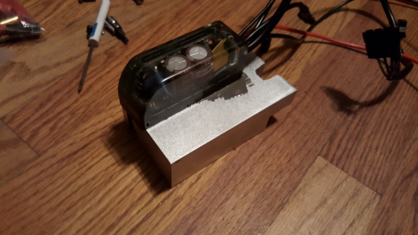
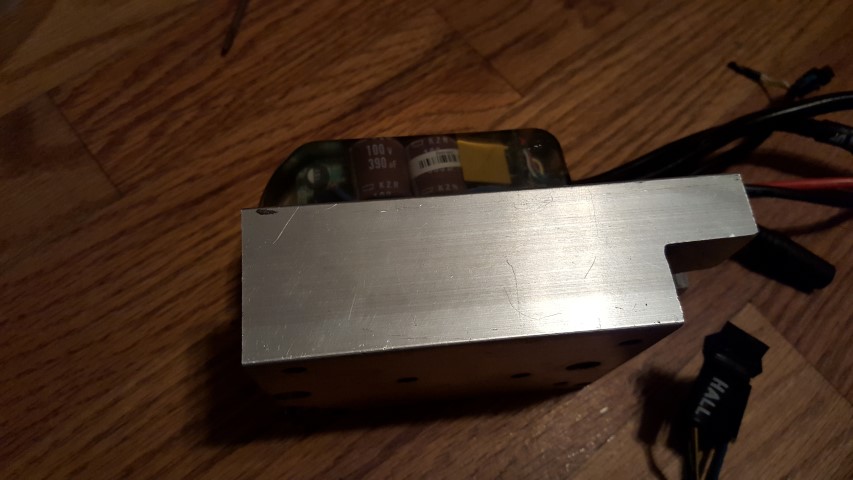
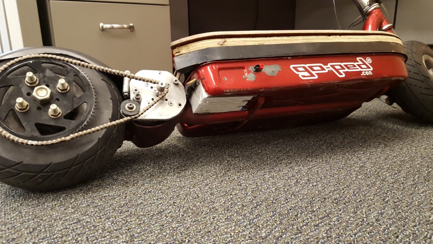
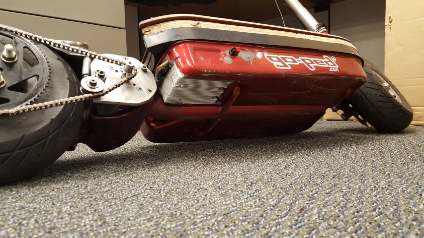
So first thing I did was order a big chunk of aluminum. The original goped controller mounted its FETs so a big block of aluminum, and then mounted that to the pan. The block sucks the heat from the controller fast, and puts it into the pan. the pan spreads the heat out into the air like a big heatsink fin.
My new setup is similar to that... I took a big block of aluminum, and cut it to fit in my controller area. This means the front edge gets trimmed to clear a bump in the pan, and one notch to fit around the mounting post. I mocked the block in place and drilled six blind mounting holes under the scooter. Took the block out, and tapped them. I then drilled the PhaseRunner mounting pattern into the top... then drilled from the bottom oversize holes so the screws could recess.
all this sounds simple, but doing it with cheap hand tools on a 4" thick block of metal is very time consuming. I wish I had a mill. No one tell the wife, but after we buy a house, I am getting an old bridgeport or something. The amount of metalwork I do with simple tools is getting silly. I want to make machinist looking parts, not hackjobs... lol Anyway, back on topic.
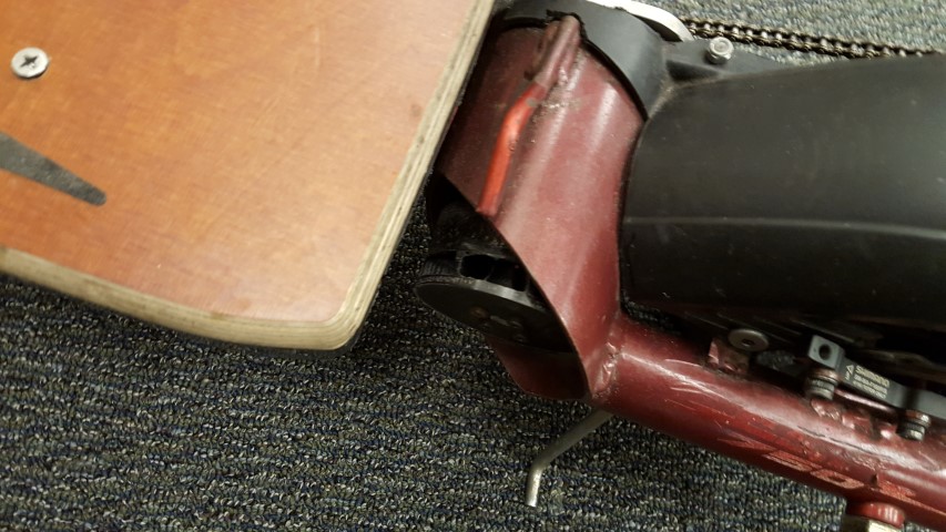
So I mounted it to the block with some thermal paste:

20150817_195020.jpg

20150817_195027.jpg


with that done I just changed the connectors to match the old one, and mounted the controller.
From there... a bit of a headache. I did the tuning steps as written online, but it kept getting instantaneous current draw errors.
I am still working on this, but I suspect the variables values for the mathematical model of the motor is far from what the controller has.
With what I have now, it seems to work most of the time. I can go 15miles without an issue... or I can go 15 yards. (24km or 13.7m for you metric readers :lol: )
I am starting to suspect that heating may be a factor... perhaps the pan isnt sufficient to always handle the heatload. I may modify it in the future.

So far I have ridden it to and from work a couple times, and around the local area.. I did ride it into downtown charleston once... its fun in downtown, but there are a couple of 45mph roads without bike lanes and they suck....

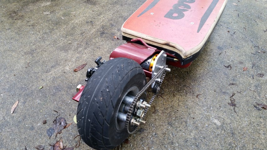
the controller limits the RPM of the motor, and combined with the tiresize and current gearing, this makes me hold at 33.1mph. If rock the scooter to go faster, you can hear/feel the motor cut out until it slows back down to the limit. I am ok with this. The the 80-100 becomes less efficient as speed goes above 9k... and will start making more heat than power.
I do want it to be a bit faster, but I think I will wait until controller cooling mods are done.

It pulls around 30-31 amps at full 33mph on level ground, at my voltage range of 66.2-59v it stays around 2000watts. According to Thud and others experience, it can sustain 3000w so I am in the safe zone there. I also have that impeller on the motor, so I am sure that helps a bunch. It doesnt pull much more going up slight hills... the minor hills that I notice on a bike, but not in a car... I dont notice on this.
Since the speed limit is RPM limited from the controller, from full battery to empty there is no change in top speed.

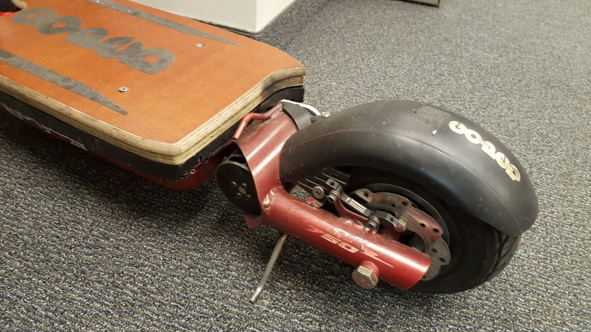
When I did the first test ride with the new controller, the magnet came off my disc brake. until yesterday, I didnt have a replacement on there.
I just looked on the CA on the way to work, and it says[strike]I get around 18wh/mi @ 33mph.[/strike] very cool, especially since I was going uphill... but I dont know if I trust that reading. seems low. I was expecting higher.
EDIT: I reset it before I left for lunch, and just got back now... its 70wh/mi @ 33mph. That sounds much more realistic. also the CA wh/mi reading is the average for the whole trip, not instantaneous like i thought.
in anycase, it get a usable 16+ah from my pack... how much more than 16, I am not sure, since I havent run it down any further than that... but the rated AH for the pack is 20. I know I wont see that, since I dont discharge them that low, or charge them 100%

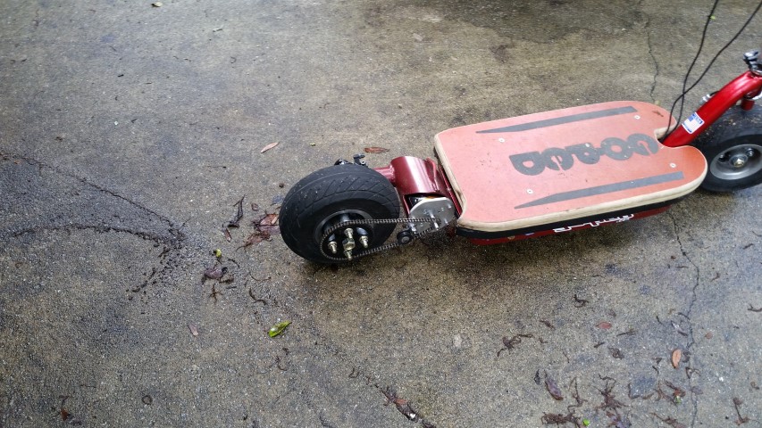
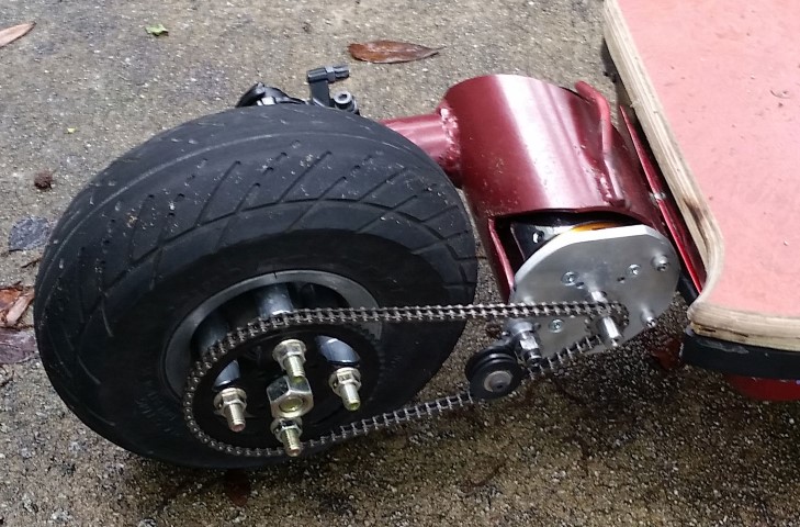
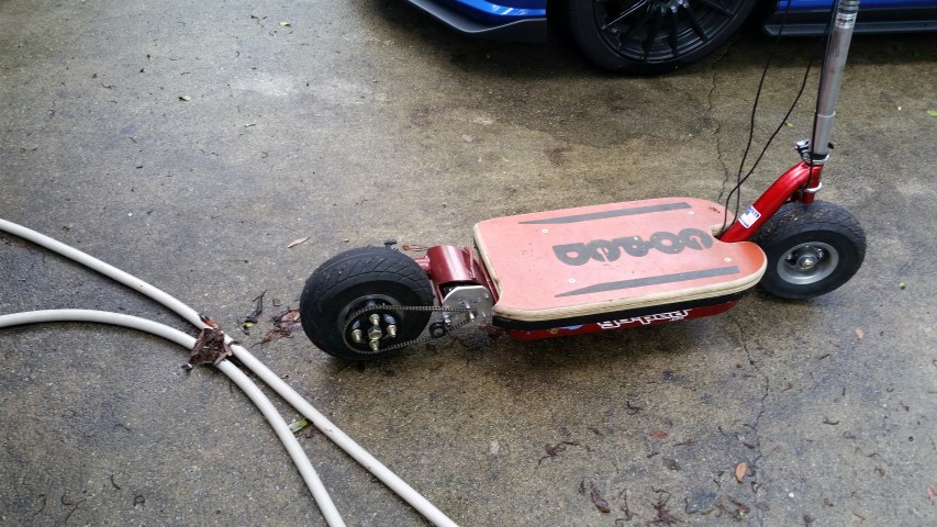
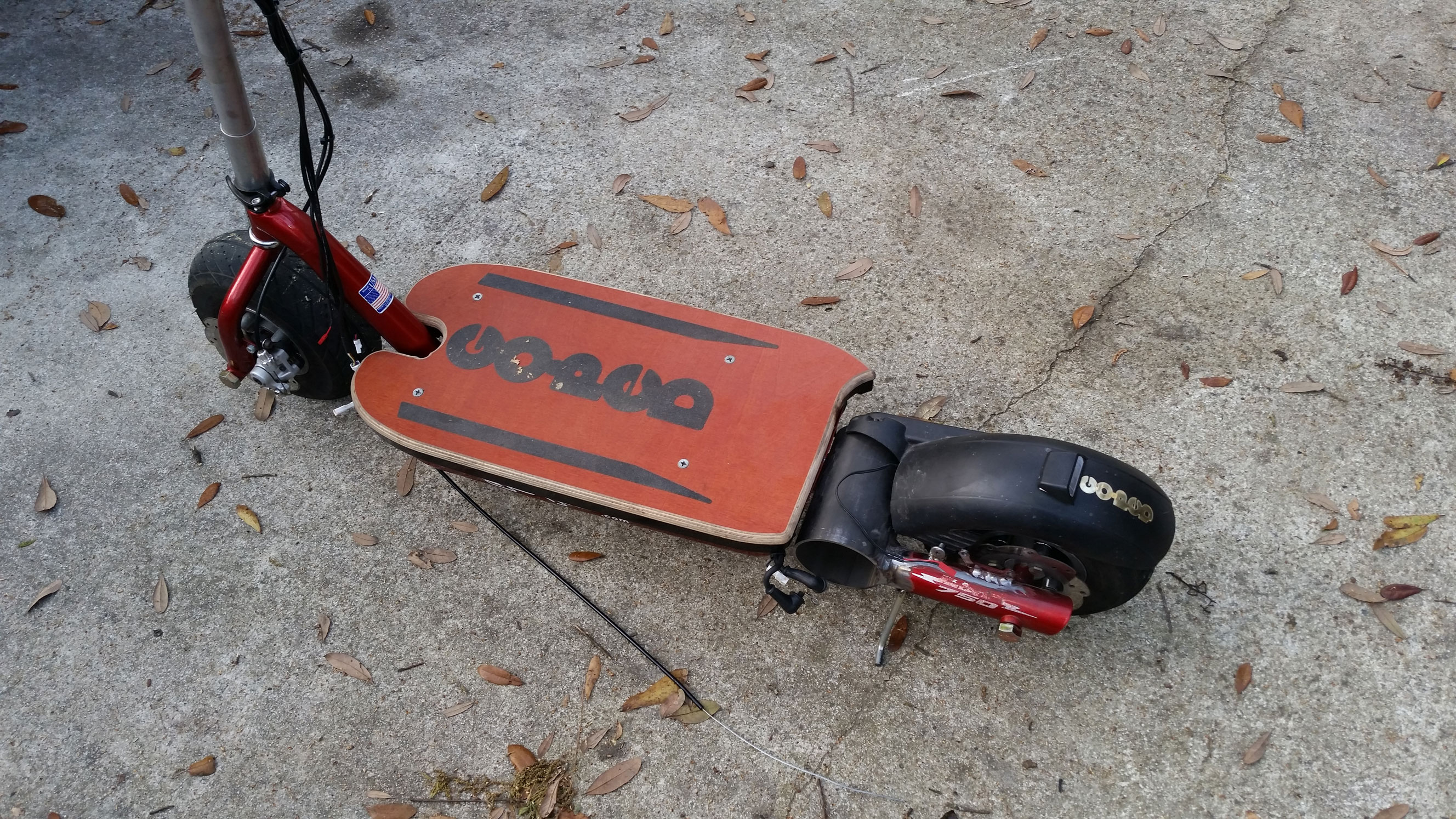
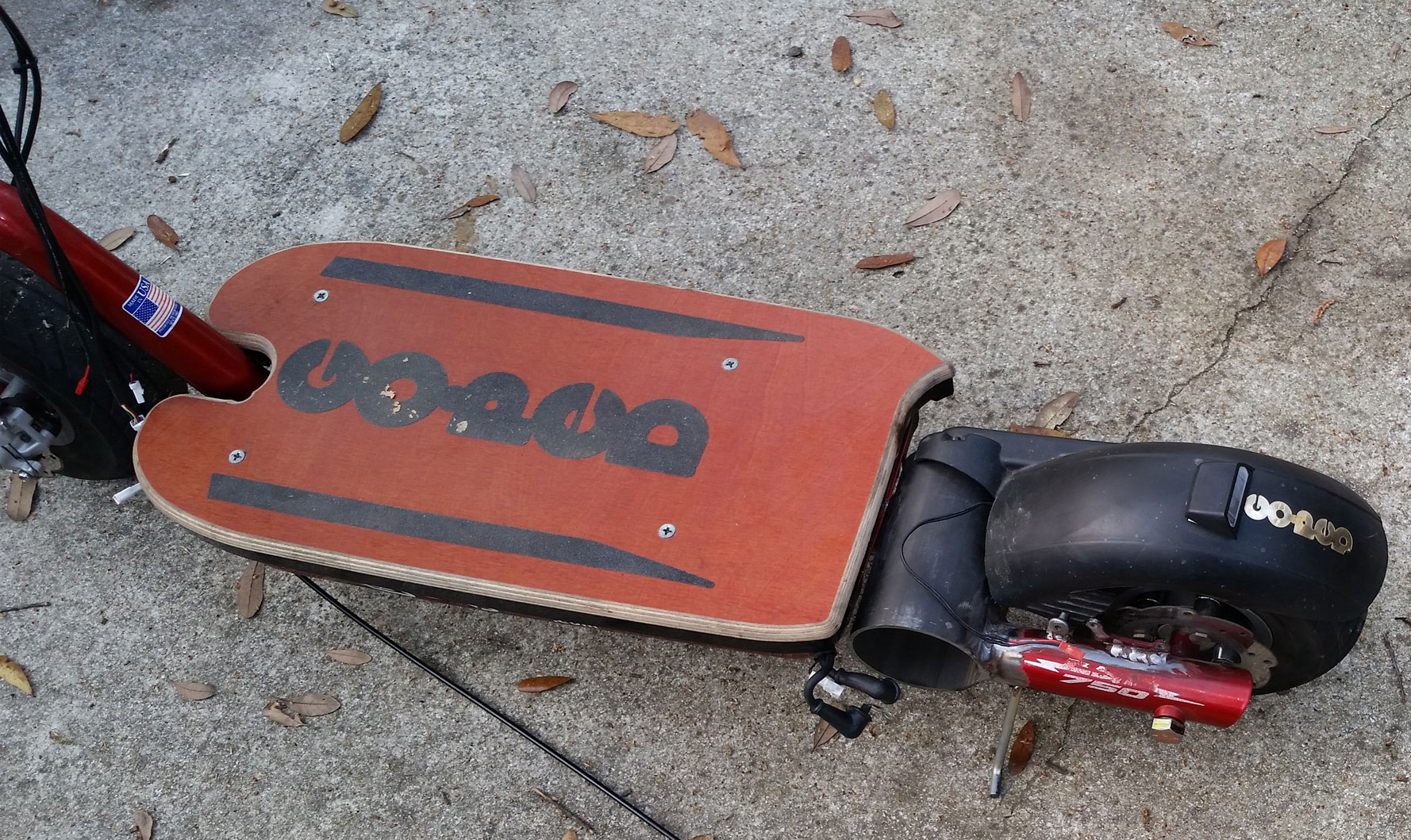
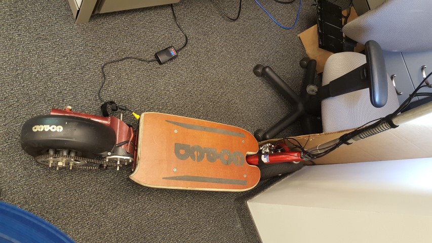
overall I like it. since I bought my new chain for the smaller high speed sprocket that I am not using, I am running the ORIGINAL chain from when this was made in 2008. it needs replacing bad. I plan on ordering today, I just need to count the links.. in 2008 there were 2 lengths it could have been. I want whatever it is I have now.
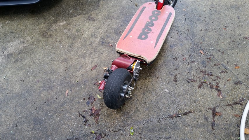
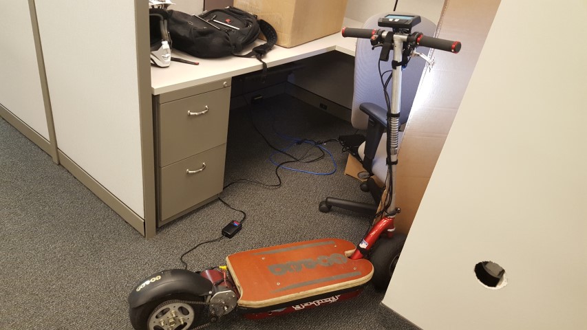
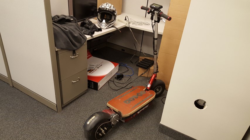
here it is at work on last friday.

20150821_141141.jpg

20150821_141202.jpg


There is still some cleanup work to be done for sure.. then when I am done hacking it, a good paintjob is in order. I like the red, but right now its a mess. work in progress for sure.


In the background of the pics above, you can see one of my new chargers. they are IBM laptop base station power supplies... 4 of them in series happens to be 66.2v. They happily push out just under 9 amps for hours on end without issue.... they do get a little warm, but you can hold your hand on them easily. Since it does Not take hours to charge, its never an issue. best part? NO FAN!!! completely silent. and I can slip them into the "laptop" slot in my backpack if I want them to go.

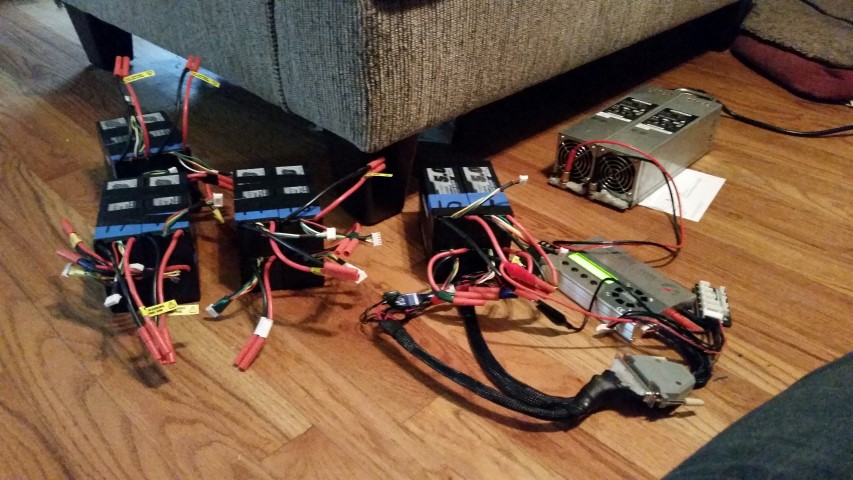
along with that, I have my home charger. a nice beastly twin meanwell SP-500-27 setup.
This was a fun build too. See, I had the meanwells together for awhile now... but as we all know, they look...welll "industrial" would be a nice way of saying it.. I have heard "bomb-ish".. and "OMG dont plug that in, there are wires".... the final straw is one of the fans in the meanwells sometimes wouldnt start.. without it going, the controller would get too hot.

so I decided to do something about that.
I'll put it up in my next post.. its lunchtime now. :lol:
 
What an *awesome* build! I just read the whole thing at lunch and wish i'd followed it earlier.

Makes me want to get a goped... But i'm going to resist and stick w/ the e-boards. Slightly slower (top speed i've done is 30mph, but that was almost flat and slight downhill), but light/portable.

Chargers - have you looked at the Dell Server power supplies? THey are ridiculously cheap and reliable. I have two in series for 24v (60'ish A), and already modded they are $70'ish. Not too shabby for 1500w!

Would love to see your travel charger setup closer!
 
sl33py said:
What an *awesome* build! I just read the whole thing at lunch and wish i'd followed it earlier.

Makes me want to get a goped... But i'm going to resist and stick w/ the e-boards. Slightly slower (top speed i've done is 30mph, but that was almost flat and slight downhill), but light/portable.

Chargers - have you looked at the Dell Server power supplies? THey are ridiculously cheap and reliable. I have two in series for 24v (60'ish A), and already modded they are $70'ish. Not too shabby for 1500w!

Would love to see your travel charger setup closer!

Yeah, I have multiple server power supplies at home.
I run two 12v, 18A supplies in series for 24v... I use it to feed my iCharger. You have to be careful to isolate them, but after that they're awesome.
I also have a box of server supplies and two massive tower supplies. I intended to sell them on here to fund project stuff, but I never got around to putting them online.

edit: this was earlier in this thread.. you can see the two chargers.
20150404_144036.jpg


I forgot to take pics lastnight, but I took my meanwells apart, and built a sealed case with 4 fans (2 in, 2 out)... added temp gauges, and made it much better. It has plenty of airflow, so that even in 90*F(32.2C) air temps, It can now run overrated without heating more than about 8*F(4.4 C) above ambient temp... best part is I did 99% of it with parts I had sitting around.

The next step for the go ped charging is a new connector for charging. I want something I can hookup so that by just the action of plugging it in, it will:
1. turn on the CA. (so the shunt can count charging, and monitor everything)
2. activate the brake input (so the scooter wont move if you bump the throttle)
3. keep the headlight off. (so Its not illuminating "steal me!" to everyone)
4. turn the charger on. (so I dont have to, I can just plug the scooter in and walk away)
5. be a cheap plug that a normal person would just plug into the scooter without question. ( no military/industrial look stuff. normal plastic preferred.)
6. accept 20a charging current. (my fastest charge rate)

since all this is similar to what cars do, I COULD use a standard car plug, but its a bit large. I am thinking I will keep the whole thing similar to car chargers, because I want the experience. however I will be using some form of smaller plug... Then I can make an adapter for any of my chargers to run off of car charge stations... as a later project.

Due to battery volume vs scooter size, I doubt I will ever have an "on board"(in board??) charger. They will always be backpack located.
 
thought I would throw an update out here.... Im commuting with the scooter every once in awhile.
20151123_142825.jpg

The 3dprinted heatsink got hit, and shattered. I had a "mirror image" one printed... so now it flows more air, at the cost of a little noise. the chain makes more noise still, so its fine.

I decided to move on to the same anderson connectors everyone else was using... so I filled in all holes in the side with thinned JB weld. its all smooth now, but I havent painted anything yet.

I ditched the "heatsink block" idea for the controller, and I cut a hole in the bottom.. it now has a flush mounted heatsink. It works excellent, however with the cooler weather, I cant tell if it made a big diff. Will have to wait until the middle of summer to know for sure. Its cool now ,53*F (11.6C) according to the internet... but on the way to work, nothing came close to warm.
heres a pic of the new bottom:.. (if you look, you can see the result of running a new chain 3 miles at 40mph and forgetting to lube it. it already has one kinked link.)
20151123_143505.jpg

20151123_143512.jpg


I also trimmed off the extra shaft coming out of the fan. I hit my ankle on it a couple times pushing the scooter, and finally decided to cut the thing. Now that its cut, I kind of wish I put the anderson connector on the back, where it used to be.
20151123_143537.jpg

20151123_143532.jpg


at some point I will repaint the whole thing. I wish I had a good way to keep the folding pole and hide the wires in it too.. maybe that will be something else to work on.
I also have been thinking lately of ditching it, and swapping the lipo, controller, and CA over to my bike, and buying a hub motor. This is fun, but a reliable hub motor bicycle would be more practical.
This is alot of fun when I can carve with it, but the controller still cuts out occasionally, and because of that I cant trust it to "power out" if you start carving down the road...
 
So I had this issue that I could just not figure out.
When I was running my other controller, I set my CA to limit my speed to 35. This way I could just hold the throttle wide open to work, and not worry about it (I commute by heavily traveled side streets)
Recently I started taking a different route home, and the speeds on this street is higher. So I went to bump it back up to 40mph.

I know that according to the CA my speed was always 32.8-33.0 and I figured I must have set the CA to 33 and didnt remember it correctly. but it was at 35.
I reset it to 40. no effect.
so I reset it to the max speed (effectively turning it off) No effect.

Well I didnt think about how I swapped over to the Phaserunner...
SO I went into the Phaserunner. I have looked at every max RPM setting, and every vehicle speed setting. I have messed with the ratios. I just cant figure out why it will NOT let me go faster than 33.
I can pump the scooter to gain speed.. until I hit that limit. then the motor actively FIGHTS me. it resists going faster.
at the 33mph cruise, the CA reads between 2200 watts to 3000 watts depending on the grade. My battery voltage under load is always above 60v. That is only 36 to 50 amps of battery pull.
the phaserunner itself is cold, and mounted to a huge heatsink directly in the airflow under it. it never gets warm, nevermind overheating.
The batteries are four 16s lipo blocks in parallel. in theory I could pull 400amps out of them without even maxing their spec.

gear ratio: 11t front on motor 76t rear wheel = 6.909 ratio
wheel size is only 9.79 inches (248.918)mm

I have messed with this and I just couldnt figure it out. I know I could gear it to go faster, but I dont want to lose acceleration if I can help it.

so then it dawns on me... I figure out the motors RPM at that point. Around 7900RPM... and divide that by the 130Kv of the motor... son of a bitch its 60v. exactly the voltage I see under load. :oops:

What I had done, was regear the scooter.. and forgot to gear it back up. When I get home tonight, I just need to swap the 11t front sprocket to the 13t one, and I can hit 40 again... or swap the rear over if I want to go even faster. :mrgreen: :lol:
 
hmm, so max is 33mph with that huge 130kv motor and 60v? Wouldn't you have enough torque with that motor and the current gearing to throw the scooter from under you if you WOT? Or did you have some settings to limit the acceleration? Or maybe all brushless do not have the low end torque that brushed have, I have a 270kv and it is terrible at accelerating until it gets around 10mph.
 
silviasol said:
hmm, so max is 33mph with that huge 130kv motor and 60v? Wouldn't you have enough torque with that motor and the current gearing to throw the scooter from under you if you WOT? Or did you have some settings to limit the acceleration? Or maybe all brushless do not have the low end torque that brushed have, I have a 270kv and it is terrible at accelerating until it gets around 10mph.

The Phaserunner controller has a ramp rate built in it, so I dont hurt myself pulling away (its like a regular goped with well charged lipo batteries) then as speed increases, it just increases the power... so it feels like it pulls away strong, but it keeps pulling and pulling.
My goal is to have a machine that is fast, but I can hand to a friend and have them ride too. Not a deathbike. lol.
With the lyen controller, it was impossible to pull away easy because the scooter would yank itself from under you before you could pull away. it was sketchy.

It is without a doubt undergeared, but I didnt notice it until yesterday... I have a 13t sprocket to put on it, but I have to drill it out to my 12mm shaft first. I went to do it lastnight, but I need to sharpen some drill bits first, and I no longer have a grinding wheel setup (I moved to a smaller garage). Im considering buying a Drill Doctor just so I dont have to mess with pulling a grinder out and figuring out a place to set it up. I dont like doing drill bits anyway.

Soon as I have it re-geared, I'll post up results... and if it looks like it can take even more gearing without issue, I'll increase it some more.

Heres a chart I made of what I have available: gearing currently in it for 33mph is 11 / 76

Code:
	Sprocket												
Pinion		56		60		64		68		72		75		76		80		82		98
	11		5.091	5.455	5.818	6.182	6.545	6.818	6.909	7.273	7.455	8.909
	12		4.667	5.000	5.333	5.667	6.000	6.250	6.333	6.667	6.833	8.167
	13		4.308	4.615	4.923	5.231	5.538	5.769	5.846	6.154	6.308	7.538
	14		4.000	4.286	4.571	4.857	5.143	5.357	5.429	5.714	5.857	7.000
	15		3.733	4.000	4.267	4.533	4.800	5.000	5.067	5.333	5.467	6.533
	16		3.500	3.750	4.000	4.250	4.500	4.688	4.750	5.000	5.125	6.125
	18		3.111	3.333	3.556	3.778	4.000	4.167	4.222	4.444	4.556	5.444
	20		2.800	3.000	3.200	3.400	3.600	3.750	3.800	4.000	4.100	4.900
	24		2.333	2.500	2.667	2.833	3.000	3.125	3.167	3.333	3.417	4.083
	25		2.240	2.400	2.560	2.720	2.880	3.000	3.040	3.200	3.280	3.920
 
Back
Top