The7 said:Does Shenzhen have the same value of R and C as V2 ?
Yes, 3.3k and .01uf.
The7 said:Does Shenzhen have the same value of R and C as V2 ?
Jozzer said:http://uk.youtube.com/watch?v=Icslk6jMyJY
Let me know if this is what you need to see, if so I'll do the rest of the controllers!
Knuckles said:From ... http://en.wikipedia.org/wiki/Brushless_DC_electric_motor (yes very noob-ish on my part) ...
A motor with windings in delta configuration gives low torque at low rpm, but can give higher top rpm. Wye configuration gives high torque at low rpm, but not as high top rpm.
The SHENZHEN controller has a jumper for choosing 60/120 degree halls as well. See fechter diagram ...Jozzer said:Thats a prototype controller made on behalf of the puma factory for their motor. I think we sent one to Fech a while back too. It was running on 60v..
I also have a Kelly 100A controller, that seemed to work quite well. At least you can choose 60/120 degree halls on the kelly.
I'll post up a vid tomorrow if I get a chance, and an analogue x'lyte for good measure.
Steve

solarbbq2003 said:if the 250watt ( or 350watt as is called) bmc is running ok on v2, and only difference to the 500watt is the coil thickness they might lead in another direction for solution, I'm guessing they are not same though, maybe 250watt is wye connected, lower nunmber of mag poles???
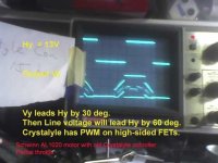
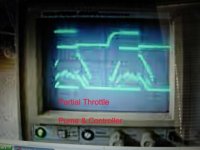
The7 said:Observations:
1) My motor phase volage is symmetrical at partial throttle.
2) The motor phase voltages of your and Fechter's look similar at partial throttle and are NOT symmetrical.
3) When free-running at throttle off, the motor voltage is symmetrical and is due its back emf.
Comments:
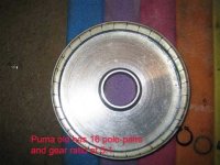
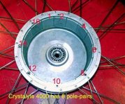
a) AL1020 motor is Y-connected and Puma is delta-connected.
b) These controllers are seemed to be designed for Y-connected motor.
c) When the phase relationship between the Hall signal and motor voltage is matched, the motor voltage will be symmetrical.
d) Suppose the phase relationship between the Hall signal and motor voltage is matched when the motor is Y-connected. Then there will be a mis-match of 30 deg in phase relationship and this would show up in an non-symmetrical voltage wavform. Seems this is case for Puma motor.
rkosiorek said:the only problem with a pedal first controller and the puma or other geared hub motor is that in order to start the pedal first combo you need to get the motor rotor turning. since the rotor is isolated from the outside hub and wheel/tire by either a freewheel or one way roller clutch ytou could never get it started.
what you would need is a combination of hall sensors used to start the motor and to take advantage at low rpm of the advanced timing for good acceleration and then at some frequency switch to a sensorless design for high speed.
rick
Knuckles said:Yes of course. You are correct. This was discussed in other threads earlier. If this was constructed ... Do you think it would work around the 'critical frequency' jitter issue or do we still have to address this with a software code fix?
Would concur with you if the Hall sensors are placed for delta connection.fechter said:I think the asymmetry is due to the advanced position of the hall sensors, not really due to being delta connected. It would be possible to locate the hall sensors in a Puma so that the timing was neutral and the waveform would become symmetrical.
From your photo, it is estimated to be about 22 deg.fechter said:IThe amount of timing advance seems to be less than 30 degrees. I have not measured it, but I could calculate it based on the geometry of the magnet poles and the location of the hall sensors. .
Would concur with Tim Obrien about his finding.fechter said:The timing advance is intentional. Tim Obrien has tested BMC motors that were both neutral and advanced timed, but otherwise identical. He much preferred the advanced version as it had better acceleration.
rkosiorek said:i think that it is an RPM thing. for a given voltage an otherwise identical motor will run at a higher RPM with the windings connected as a DELTA and lower RPM when connected as a WYE (star). the RPM is at the expense of torque though.
the power produced by either winding configuration will be the same though. power is analogous to RPM X Torque. so the Delta with higher RPM and lower torque would produce the same power as the WYE would using lower RPM but higher torque.
i would guess that in the PUMA/BMC they needed the Higher RPM to turn the wheel at an acceptable speed after the gear reduction and the gear reduction would more than compensate for lack of torque.
rick
rkosiorek said:So for any given voltage the Delta will run faster than the WYE. so for an ebikes the design is limited by the Voltage of the battery pack. a DELTA wired motor will run faster on 24V or 36V than one wirred as a WYE.
Rick
rkosiorek said:the question would be "IS IT WORTH THE EFFORT" to rewind one motor for yourself. think of it. cut off the old wiring, strip all traces of the shellac and paper insulators from the stator teeth, cut new insulators from paper, rewind all of those coils, re-dip the whole mess in shellac to fix the coils in place, re-mount the hall sensors.
rick