Version 2 Crystalyte Controller information

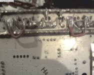
and another part of the Circuit is the Power LED. it is no longer just a Power LED. it has it's own circuit board now and connects to a dedicated output pin on the Cypress controller chip.

for the power LED to turn on, the battery power must be ON and output Pin #25 on the Cypress controller has to be held High for the LED to turn on. this is for the Error codes.

View attachment 1

not 100% sure or tested but i think these are the Error Codes:
Indicator light on steady: Normal working
Indicator light on: EABS braking status
Indicator light on for 0.5 second - flash 1 time - off for 1 second: Standby status
Indicator light on for 0.5 second - flash 2 times – off for 1 second: Brake signal
Indicator light on for 0.5 second - flash 3 times – off for 1 second: MOS damage
Indicator light on for 0.5 second - flash 4 times – off for 1 second: Immediate start at high speed protection
Indicator light on for 0.5 second - flash 5 times – off for 1 second: Electric current failure
Indicator light on for 0.5 second - flash 6 times – off for 1 second: Power supply’s low voltage protection
Indicator light on for 0.5 second - flash 7 times – off for 1 second: Hall effect signal failure
Indicator light on for 0.5 second - flash 8 times – off for 1 second: No throttle signal

this circuit board is quite small and is covered in a piece of heat shrink that is glued into the endplate so the LED peeks through and is visible on the outside.

rick
 

Attachments

  • POWER LED BOARD.pdf
    14.7 KB · Views: 128
Location of the LVC resistor on the board:

35a controller 29V LVC-web.jpg

rick
 
here is the circuit for the current limiter

CURRENT LIMITER.jpg

on one of the controllers I modified the current limit up to 50A by placing a 0.025ohm 3W resistor in parallel with the pair of wire shunts. that was sort of big and clunky.

on a different controller i left the shunt resistor alone. instead i changed the Value of R4 from 1.2K increasing it to 1.5K. this has the same effect in bench testing.

35a controller 29V LVC-web.jpg

since the picture was taken i have also made the following changes.:
1. i filled all 12 FET locations with IRFB4110 FETs. all of the circuitry to drive them is already on the board.
2. all 3 of the filter caps are now 1000mfd 100V LOW ESR units.
3. added a reverse biased 40A schottky diode across the battery input. this does 2 things. it protects the controller from reverse polarity battery errors. also when running certain motors (BMC geared hub in particular) i saw a lot of reverse voltage spikes. i think that these spikes may be what killed the filter capacitors in the first place. so i added the diode to shunt these spikes around the controller.

when i get time i'll take some pictures of these mods.

rick


rick
 

Attachments

  • CURRENT LIMITER.pdf
    14.2 KB · Views: 191
on a different controller i left the shunt resistor alone. instead i changed the Value of R4 from 1.2K increasing it to 1.5K. this has the same effect in bench testing.

What was the original current limit, and the resulting limit after? The relationship between the R4 value and the actual current limit is linear, correct?
 
not quite linear. the original limit was around 37A. so i guess you could call it a 35A controller or a 40A controller depending on the mood of the advertising department.

the drop across R4 must equal the voltage drop across the shunt at the rated current. for 50A the drop across the shunt was 0.35V.

R4 in series with a 20K resistor forms a voltage divider connected to the 5V supply. to get the required 0.35V R4 must be a 1.5K.

the original 1.2K resistor would form a 0.245V voltage divider. 0.245V across the shunt occurs between 35 and 40A.

rick
 
Are you sure about those numbers? Those shunt voltage drops put the shunt resistance at around 7miliOhms. That sounds too high, since the v1 controllers had a shunt resistance of about 1miliOhm.

Would it be accurate to say that the comparator is sending ~0.2mA through R4, and backing off the PWM when the voltage drop across the shunt is equal to or greater than that of R4?

Thus, if a 100A limit was desired, R4 should be increased to 3.5k? Or a nice 1k-5k trim pot would do the trick. Or reinforcing the shunt with some solder and aa 600-1.2k trim pot in place of R4 would provide a nice increased current limit adjustable downwards. Very, very nice.

This is extremely useful information.
 
excellent info guys!
rick did you notice fets 3 and 7 there is no connection on one leg of the fets??
I put some thin high amp wire ( type used in some motors to come out axle ) to connect them to the main battery power ( sorry dont know correct names to identify the parts pic attached shows what I mean)
also can put new fets in without removing all the solder, can get old ones out pretty easy just put iron on all 3 legs at one time,
had to open out all the holes on board for fets with think screwdriver and solder iron, then can reuse existing thick bits of solder on board
 

Attachments

  • fet3 and 7 add shuntsmall.jpg
    fet3 and 7 add shuntsmall.jpg
    40.5 KB · Views: 3,079
this controller will run bmc rick?? was under the impression this one would not run bmc motor? or is it specifically only the 500watt version bmc that has probs ?
 
My understanding is that it *might* run a BMC, but that others have had problems with the v2 units. There's some sort of software limitation that these units have with respect to high commutation frequencies. Since the BMCs are geared and run at a much higher RPM, they have had problems with these units. Not a hardware thing at all, but an example of Crystalyte shortsightedness.

And, regarding the missing FET leg connection... what the hell? I had overlooked that. So, those are two low-side FETs that don't have a good connection from drain to ground. My DVM says that they are in face connected to ground and thus functioning correctly, but wherever that connection is actually made, it has to be flimsy. It should be reinforced.
 
lazarus2405 said:
My understanding is that it *might* run a BMC, but that others have had problems with the v2 units. There's some sort of software limitation that these units have with respect to high commutation frequencies. Since the BMCs are geared and run at a much higher RPM, they have had problems with these units. Not a hardware thing at all, but an example of Crystalyte shortsightedness.

I suspect that the issue is more of a BMC thing. the controller is designed for neutrally timed motors. the placement of the hall sensors on the BMC suggests that the Hall sensor timing is advanced a few degrees. that would explain why the motor runs fine at low rom but develops a timing problem at high rpm. but this is an untested theory at this time.

lazarus2405 said:
And, regarding the missing FET leg connection... what the hell? I had overlooked that. So, those are two low-side FETs that don't have a good connection from drain to ground. My DVM says that they are in face connected to ground and thus functioning correctly, but wherever that connection is actually made, it has to be flimsy. It should be reinforced.

Unlike the old analog controller where the copper traces exist only on the top and bottom of the board (so we can actually see all of the traces), the V2 board is a 4 layer board. there are 2 more layers of copper sandwiched inside there that we cannot see. one of those layers is a ground plane that connects all of the ground points in the board. that is a large amount of copper and more than sufficient to carry the current for the short length needed to go to those 2 FETs from their neighbors.

rick
 
that is a large amount of copper and more than sufficient to carry the current for the short length needed to go to those 2 FETs from their neighbors.

I am skeptical. How many amps do you think it's good for? I'm talking about reinforcing it for operation >50a.
 
lazarus2405 said:
Are you sure about those numbers? Those shunt voltage drops put the shunt resistance at around 7miliOhms. That sounds too high, since the v1 controllers had a shunt resistance of about 1miliOhm.

Would it be accurate to say that the comparator is sending ~0.2mA through R4, and backing off the PWM when the voltage drop across the shunt is equal to or greater than that of R4?

Thus, if a 100A limit was desired, R4 should be increased to 3.5k? Or a nice 1k-5k trim pot would do the trick. Or reinforcing the shunt with some solder and aa 600-1.2k trim pot in place of R4 would provide a nice increased current limit adjustable downwards. Very, very nice.

This is extremely useful information.

when i measured the shunt resistance by putting a 1 amp controlled current through the shunt the voltage drop was 0.007V meaning it is 0.007 ohm. i could have made an error in my method but i don't think i did.

that comparator feeds a "digital only" input pin12 of the CYPRESS chip. that would be an absolute on/off type of current limit. the other half of the comparator that is configured as a X10 amplifier that feeds analog input pin 8 does the "Foldback" current limiting. i had thought of increasing the value of R63 to reduce the amount of amplification and the "Foldback" effect but i have not had a chance to do that yet.

rick
 
I suspect that the issue is more of a BMC thing. the controller is designed for neutrally timed motors. the placement of the hall sensors on the BMC suggests that the Hall sensor timing is advanced a few degrees. that would explain why the motor runs fine at low rom but develops a timing problem at high rpm. but this is an untested theory at this time.

This makes more sense than "huh, crystalyte screwed up". I always thought that any controller should be good up to the 1khz range.
 
lazarus2405 said:
that is a large amount of copper and more than sufficient to carry the current for the short length needed to go to those 2 FETs from their neighbors.

I am skeptical. How many amps do you think it's good for? I'm talking about reinforcing it for operation >50a.

It has got to have a lot more cross sectional area. Larger than the FET leads do. especially thicker than the connection from the lead to the die internal to the FET. cross sectional area is what is important, this one may be thin but for the most part it is a wide as the board is. lots of cross sectional area.

but you may be right, it is probably more than adequate for the intended design limits of 40 or 50 amps but not enough for 70 or 80 amps. for the "Ludicrous Speed" (remember "Space Balls") crowd it would not hurt to add a couple of bit of copper.

rick
 
rick the board has no 'visible' connection to the thick solder on two fets on the outer leg which takes high amp ( sorry i dont know name of the leg........source/drain not sure), unless there is a connect in another layer but doubt that. Seems just wasn't designed into the board need a shunt for two of those fet legs ( unless i'm missing something obvious!!!). From left its number 3 and number 7 fets when looking down on board same view as in pic you posted. But soldered shunt as per my pic all works fine.
 
one other thing on max amps of board, assuming it was about 37amp limited, when controller had 6 lots of 4310 fets, you can see where solder blew off board, so I assume about 37amps going through that leg and solder, so definitely lower than 72amp for a 12 fet setup, seems to be restricitive the solder where it joins to some fet legs is very narrow amount of solder. could always beef up the solder at those points though
 
Solar, those two legs are each a drain on a low side fet. The source leg connects to the motor phase, and drain goes to battery ground. Though there is no visible connection, my multimmeter shows a good connection between those legs and ground. It is cinnected without needing any modification.

I added as much solder as I could between each fet leg and the respective bus. I think I'll go back and add some copper strand, to be safe.
 
the board has 4 layers of copper separated by thin sheets of fiberglass. those legs connect on one of the hidden inside layers. but go ahead add some external wire if you must.

rick
 
Crystalyte controller wiring.
NOTES 1. PAD LABELS PRINTED ON BOARD ARE ENCLOSED IN BRACKETS
E.g. (FSD) = pad labeled FSD on board
2. pigtail wires listed in order of pins on connector.
E.g. 3-Wire Throttle Pigtail 3 pin female – Red, Black and Green
RED = PIN#1
BLACK = PIN#2
GREEN = PIN#3
3. board is oriented parts side up with FETS farthest away from you.

Battery connector Red and Black 14AWG wires
Red – (D+) – near shunt
Black – (D-) – beside shunt

Power Switch 2 pcs Red hookup wire
Red #1 – (D+) – beside Red Battery wire
Red #2 – (L) – beside low voltage regulator circuit.

Reverse Pigtail 2 pcs blue hookup wire
Blue #1 – (D-) – Beside Black battery wire
Blue #2 – (DSP) – to right of Low voltage cutout circuit.

Motor Phase Wires Blue Green Yellow 14AWG
Green – (A) – beside shunt – left edge of board
Blue – (B) – middle of board
Yellow – (C) – right edge of board

LED Board 4 wires – Yellow, Blue, White and Black
Yellow –(L) to (2N) on LED Board
Blue – (FCD) to (11PIN) on LED Board
White – (Throttle Pigtail Pin 4) to (OUT) on LED Board
Black – (GND) to (GND) on LED Board

4-Wire Throttle Pigtail 4 pin female – Red, Orange, Yellow and White
Red - (+5V) to (Pin 1) on Throttle Pigtail
Orange - (GND) to (Pin 2) on Throttle Pigtail
Yellow - (SP) to (Pin 3) on Throttle Pigtail
White - (OUT on LED Board) to (Pin 4) on Throttle Pigtail

3-Wire Throttle Pigtail 3 pin female – Red, Black and Green
Red - (+5V) to (Pin 1) on Throttle Pigtail
Black - (GND) to (Pin 2) on Throttle Pigtail
Green - (SP) to (Pin 3) on Throttle Pigtail

Cruise Control Pigtail 5 pin male – Red, Orange, Yellow and White Pin 5 unused
Red - (+5V) to (Pin 1) on Cruise Control Pigtail
Orange - (GND) to (Pin 2) on Cruise Control Pigtail
Yellow - (SP) to (Pin 3) on Cruise Control Pigtail (THROTTLE)
White - (HL) to (Pin 4) on Cruise Control Pigtail (BRAKE)
Pin 5 – unused

Hall Sensor Motor Lead 5 pin female metal connector – Red, Black, Yellow, Brown Blue
5 inline pads immediately to the right of the CYPRESS oriented vertically. pin #1 at bottom
Red – pin #2
Black – pin #1
Yellow – pin #3
Brown – pin #4
Blue – pin#5


3 different versions of the brake inhibit connection exist.
Listed in chronological order oldest to newest.

Brake Inhibit Pigtail 3 pin male – Red, Black and Green
Red - (+5V) to (Pin 1) on Brake Inhibit Pigtail
Black - (GND) to (Pin 2) on Brake Inhibit Pigtail
Green - (HL) to (Pin 3) on Brake Inhibit Pigtail

Brake Inhibit Pigtail 3 pin male – Red, Black and Green
Requires board modification. R39 (20K) removed and is replaced with a 1N4148 diode. The cathode is pointing to the bottom edge of the board. R39 is located beside the pad labelled XS
Red - (+5V) to (Pin 1) on Brake Inhibit Pigtail
Black - (GND) to (Pin 2) on Brake Inhibit Pigtail
Green - (XS) to (Pin 3) on Brake Inhibit Pigtail

Brake Inhibit Pigtail 3 pin male – Red, Black and Green
5 inline pads immediately to the right of the hall sensor pads oriented vertically. pin #1 at bottom
Red - (CDL pin#1) to (Pin 1) on Brake Inhibit Pigtail
Black - (CDL pin#2) to (Pin 2) on Brake Inhibit Pigtail
Green - (CDL pin #3) to (Pin 3) on Brake Inhibit Pigtail
 
greasypants said:
Managed to get the controller working - two of the mosfet insulating washers needed to be replaced.

Here are the controller codes from Justin if anyone needs them.

V2 Controller Indicator Status Instruction

 Indicator light off: Normal working
 Indicator light on: EABS braking status
 Indicator light on for 0.5 second - flash 1 time - off for 1 second: Standby status
 Indicator light on for 0.5 second - flash 2 times – off for 1 second: Brake signal
 Indicator light on for 0.5 second - flash 3 times – off for 1 second: MOS damage
 Indicator light on for 0.5 second - flash 4 times – off for 1 second: Immediate start at high speed protection
 Indicator light on for 0.5 second - flash 5 times – off for 1 second: Electric current failure
 Indicator light on for 0.5 second - flash 6 times – off for 1 second: Power supply’s low voltage protection
 Indicator light on for 0.5 second - flash 7 times – off for 1 second: Hall effect signal failure
 Indicator light on for 0.5 second - flash 8 times – off for 1 second: No throttle signal


Could anyone explain the exact meaning of "Electric current failure" or "MOS damage"? Thanks.
 
MOS damage is Chinese for MOSFET. ie the FETs. I don't know what the electric current failue is.

rick
 
Back
Top