What can a Grin controller + cycle analyst do that KT controllers + KT display can't do?

amberwolf said:
The CA (Cycle Analyst) doesn't multiplex any signals. It has a completely separate wire set for the temperature sensor and the speed sensor, and completely separate inputs on it's internal MCU as well.

But does the CA display temperature from their own compatible controllers that multiplex?

It seems like it should. At the very least multiplex is happening as they explicitly state it on their website.

https://ebikes.ca/shop/electric-bicycle-parts/motors/mg311-standard-wind-unlaced.html
Uses 9-pin overmolded Higo Z910 waterproof connector for the motor phase, hall, and combined speedo and thermistor wires.

https://ebikes.ca/shop/electric-bicycle-parts/motors/shengyi-x1-helical-geared-motor-standard-wind.html
It uses our new combined speed and thermistor signal system allowing both speed sensing and thermal rollback from one wire of the Z910 plug. This feature is compatible with 2020 model Baserunner_Z9 controllers using a CA3-WP display.

If I were to guess, this multiplexing is not Grin's "invention" but rather something that came from Chinese manufacturers. Since the Z910 plug is a very common 9-pin plug on small to mid size motors, they simply didn't have an extra pin to NOT multiplex.

And I imagine that KT controllers follow (or can follow) the same strategy because there is simply no extra pin. And it's "them" that probably came up with multiplexing to begin with.

Thoughts? :mrgreen:
 
Thought?

Let's not confuse what's possible with what "is".
My thought is that although it's possible (anything is possible given the money and determination), from a more practical standpoint, it hasn't happened yet.

Unless you have plans to change that, lets move on?
 
AHicks said:
Thought?

Let's not confuse what's possible with what "is".
My thought is that although it's possible (anything is possible given the money and determination), from a more practical standpoint, it hasn't happened yet.

Unless you have plans to change that, lets move on?

Maybe you can leave your phone number and we'll text you when we figure this out? :mrgreen:

Voicing your skepticism for the 10th time doesn't add anything to this discovery process. :lol:
 
afaik CA collects all its data inputs directly from compatible sensors

and does no communications with **any** controller, other than its modified throttle input. Grin controllers may well be an exception of course since they have control over both sides.

So there is no issue of controllers being "compatible" or not, they all are. Just that some like Nucular state they are so featureful that they simply have no use for CA

Multiplexing signals is very old school tech, been around well over a century, long before any eBikes

But there are hundreds of methods, protocols, it is not just one thing.

afaik there is nothing special about KT wrt CAv3
 
john61ct said:
Multiplexing signals is very old school tech, been around well over a century, long before any eBikes

Sure, there is no nothing revolutionary about multiplexing, but someone started using it first in the context of a hub motor, a temperature sensor, and a speed sensor, because there wasn't an extra ping available. So whoever started using it first deserves "invented" in quotes for it. :lol: If enough companies go with this method it might become a de facto standard that makes it into all mainstream products in the future.

john61ct said:
afaik CA collects all its data inputs directly from compatible sensors
and does no communications with **any** controller, other than its modified throttle input. Grin controllers may well be an exception of course since they have control over both sides.

Looking at the pinout on the plugs for the 2020+ Baserunner_Z9, it seems like what is happening in the Grin ecosystem is the motor multiplexes speed+temp, sends the multiplexed signal to the controller, then the controller splits up that multiplexed signal and sends speed on one wire, and temp on another wire to CA.

So I guess I'd still be interested in how the multiplexed signal from a Grin motor actually looks like on a scope. This might help with figuring out what a KT controller expects as a valid multiplexed signal.

Tangential question for ebike gurus here, why is there a separate hall for speed? What's wrong with using one of the three hall sensors used for commutation as a speed sensor also?

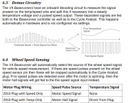
EDIT: I should have kept reading the Basetunner_Z9 manual. The answer was on page 21 of 26.

grin_demuxing.png
 
Comrade said:
But does the CA display temperature from their own compatible controllers that multiplex?
I don't see how, unless the controllers demultiplex the signal for the CA first, given the wiring specified on the CAv3 page. Certainly none of the CAv3s I've got can do the demuxing; they all have separate input wires, but none of them are from the last couple years; perhaps they have changed things without changing the documentation?


It uses our new combined speed and thermistor signal system allowing both speed sensing and thermal rollback from one wire of the Z910 plug. This feature is compatible with 2020 model Baserunner_Z9 controllers using a CA3-WP display.
Then that must mean that specific Baserunner is doing the demultiplexing and then sending the separate signals to the CA, or else they have a completely separate CA version just for those, than the regular one documented on the page I linked. Or the page is not up to date and doesn't include the new information. Any or all of those is possible.


And I imagine that KT controllers follow (or can follow) the same strategy because there is simply no extra pin. And it's "them" that probably came up with multiplexing to begin with.

Thoughts? :mrgreen:

No idea on the KT stuff. Without information from the manufacturer specifying how to implement that, or testing a KT using a motor already known to multiplex the signal to see if it "just works" with that version of multiplexing, then you'd have to come up with testing methods to generate various ways of multiplexing the two signals together and seeing if the KT detects any of them (without damaging it's sense line).

A question comes up of whether the multiplexed version of the signal line is backwards compatible with the separate signal line(s), such that it could still be used for a speed sense only type of motor, and also be used with the multiplexed signal version. It may require different firmware in the controller to interpret this, or it may even require different hardware on the controller's sense line to demultiplex the signal.

Depends on how they actual do the signal multiplexing. And since there are multiple ways to do that (including encoding them both in a serial data channel), then if more than one way is used by different manufacturers, it's certainly possible that not all controllers capable of demuxing one type of signal could do it for any other type, so it could require a specific controller to work with a specific motor.


Need specific details on everything to know what's compatible, what's not, and how it works, to be able to test anything.
 
Comrade said:
Looking at the pinout on the plugs for the 2020+ Baserunner_Z9, it seems like what is happening in the Grin ecosystem is the motor multiplexes speed+temp, sends the multiplexed signal to the controller, then the controller splits up that multiplexed signal and sends speed on one wire, and temp on another wire to CA.

So I guess I'd still be interested in how the multiplexed signal from a Grin motor actually looks like on a scope. This might help with figuring out what a KT controller expects as a valid multiplexed signal.

Tangential question for ebike gurus here, why is there a separate hall for speed? What's wrong with using one of the three hall sensors used for commutation as a speed sensor also?

EDIT: I should have kept reading the Basetunner_Z9 manual. The answer was on page 21 of 26.

grin_demuxing.png
Thanks--that is useful info. Tells us at least how that specific version of signal muxing works. I suspect they are using the thermistor itself as the pullup resistor for the speedo hall signal, inside the motor (but without seeing the hardware inside the motor, dunno for sure).

It's still possible to mux them in other ways (probably some I haven't thought of) that aren't compatible with the demuxing method used above, and some that wouldn't be backwards-compatible with a regular speedo input (though this method probably is).


Tangential question for ebike gurus here, why is there a separate hall for speed? What's wrong with using one of the three hall sensors used for commutation as a speed sensor also?
Most geared hubs freewheel when not under power, so the motor commutation halls won't be providing any speed signal.

Non freewheeling hubs don't need a separate speed sensor, but the freewheeling ones, and middrives, do.
 
amberwolf said:
Thanks--that is useful info. Tells us at least how that specific version of signal muxing works. I suspect they are using the thermistor itself as the pullup resistor for the speedo hall signal, inside the motor (but without seeing the hardware inside the motor, dunno for sure).

Hi,

The NTC fitted in the motor(s) that Grin sell are actually connected as a pull *DOWN* resistors. It is essentially connected between the ground, and the signal pins of the speed hall sensor so that it's output is multiplexed with the speed signal on the white wire.

A potential divider is formed with the upper resistor (R1) being the 5k pullup resistor in the CA, and lower resistor (R2) being the NTC.
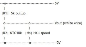
ascii-diagram.JPG

The temperature component is encoded in the amplitude of the square wave. I don't have a capture of the oscilloscope trace, but suffice to say that it looks very much like a regular square wave with a Vmax of between 0.5V to 3.3V and a Vmin of around 0V. Just visually observing the trace really doesn't show much because the temperature component changes so slowly.

The diagram that Grin uses to illustrate this is actually an accurate illustration of what the wave looks like:

combined-speed-temp-signal.JPG

If you measure the square wave you will see that the lowest part of the square wave is always around 0.13V or thereabouts (the offset described below), and the top / peak of the square wave is a voltage that changes with temperature which is around 3.33V at 25 deg C. and reduces to 0.58V at 100 deg C. when using a B3900 thermistor.

It is perfectly possible to retro-fit thermistors like this in other models of motor. I have successfully done this serveral times and had the signal successfully de-multiplexed by the Baserunner and displayed correctly by the CA. It is worth confirming that at the present time, Baserunner Z9 is the only controller (that I know of) that does this de-multiplexing. The Baserunner L10 and the Phaserunner both do not do this because they have separate temperature wire inputs.

When using this scheme, I noticed that the temperature displayed on the CA had a small error. The CA would under-read the motor temperature slightly. This error was being caused by a very small voltage drop in the ground wire. This voltage drop was present because of the return current from the hall sensors in the motor sharing the same ground line as the temperature signal was using for it's reference ground.

This caused Vout to have a DC offset of around +0.13V which translated into around a 6.5 degree under-reading at 100 deg C. motor temp.

I corrected for this by using a slightly higher Beta value thermistor which caused the voltage to be pulled down a bit further as the temperature increased. I found that using a 10K B4100 thermistor reduced this error to less than 1% at 100 deg C.

I remember Comrade is interested in Aikema motors from another thread, so I have included below some photos of a thermistor retro-fitted inside an AKM-74SX motor. The wires are soldered to the capacitor because it was already connected across the hall output and it has much larger pads to solder to than the actual hall sensor and this was the easiest place to solder them.
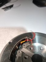
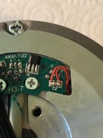
akm-thermistor1.jpg
akm-thermistor-2.jpg
 
AHicks said:
Comrade said:
It is on the white wire that in theory temperature gets "multiplexed", if the motor has an internal temperature sensor tied in with the speed hall sensor.

I believe that my friend, is wishful thinking. If you show me a KT display successfully displaying a motor temp. THEN I'll believe you.

To answer your earlier question about whether it is possible for a KT controller to display motor temperature:

While it is theoretically possible for a KT controller to display a motor temperature on the display and the KT LCD3 & KT LCD8 displays do have a placeholder for motor temperature. Sadly, in all of the 6-FET KT controllers that I have taken apart it is electrically impossible for the KT controller to read this signal from the white wire without modification.

This is because the white wire is internally connected to PIN 30 (PC5) of the STM8 microcontroller. This is a digital only pin which is not internally mappable to the ADC. This means that it is electrically impossible for the stock KT controller to read the amplitude of the square wave described above which is required to demultiplex the temperature signal.

If you were to modify the controller by moving the white wire internally to another microcontroller pin, (there are two spare analogue pins on the microcontroller, and at least one of them is broken out on the PCB to pad X4) then it would be electrically possible for the controller to demultiplex this signal, but it would require a firmware change to do this.

So, in theory, yes, it would be possible to display accurate motor temperature on a KT controller, but you would have to move the white wire to PCB pad X4, then install Casaino's open-source firmware, then write some extra code to sample pin voltage and demultiplex the signal. I haven't seen anyone do this yet.

thanks,
Oli.
 
Oli.Hall said:
While it is theoretically possible for a KT controller to display a motor temperature on the display and the KT LCD3 & KT LCD8 displays do have a placeholder for motor temperature. Sadly, in all of the 6-FET KT controllers that I have taken apart it is electrically impossible for the KT controller to read this signal from the white wire without modification.

This is because the white wire is internally connected to PIN 30 (PC5) of the STM8 microcontroller. This is a digital only pin which is not internally mappable to the ADC. This means that it is electrically impossible for the stock KT controller to read the amplitude of the square wave described above which is required to demultiplex the temperature signal.

I found a schematic online for the 6-FET KT and it is indeed pin 30. My 12-FET is probably identical on the CPU side.

View attachment S06S_controller_schematic.pdf

When I was trying to feed a simulated multiplexed speed+temp on the white wire, speed readout on the display dropped to 0 when Vmax went below around 3V, which does suggest it is indeed connected to a digital pin. I didn't look at the traces at that point, but was hoping that maybe it was AC coupled, as speed readout was the same at 5% square wave duty cycle, and 95% duty, and removing some small capacitor somewhere would open up the ADC.

I received a response from the email address that is silk screened on my controller PCB.

If there is letter “C” on your controller label, the controller has temperature function.

So I'm not sure if they mean the label on the outside case, or on the PCB.

kt-pcb.jpg

I'm not around my workbench to confirm the sticker on the case, but probably no C on it.

At this point I'm kind of resolved to sticking something like an Arduino in the controller case anyway. That way I could have the temperature field on the display cycle through several temp sensors. The code for such a contraption was already posted here on Endless-Sphere and it's much easier than I thought.

And then there is no need for analog temp sensors and dealing with calibration. A digital temp sensor like the DS18B20 would be an interesting substitution.
 
Comrade said:
So I'm not sure if they mean the label on the outside case, or on the PCB.

They mean the label on the case. The boards are all the same, but the firmware is different for different versions of the controller that expect to recieve different inputs, including input on pad X4. For example, there used to be a controller called an S06ST that was compatible with a torque sensor which was connected to pad X4.

I don't have an LCD3/LCD8 on hand to try this, but you could try connecting a 10k resistor between pad X4 and ground to see if the installed firmware recognises this as a temperature input. It's a long shot, but it's worth a try.

This pin is not detailed on the S06 schematic, but on the 12-fet board it is connected to microcontroller Pin 15 (AN7) through a 2.2k series resistor. This pin has a 2.2k pull-up and a smoothing cap both connected to +5V.
 
I have kt controller and there is a way to show motor temp in display. In Kt protocol there is dedicated bytes for temp. But in default controller send only +15c value to display. So if you activate motor temp in display it always show +15 celsius. I added arduino between controller and display. Arduino is reading temp from motor temp sensor and feed that temp data to data packets going to display. So it read what controller send, add temp and pack it again and send display.

There is code that i use. I use Dallas DS18B20 temp sensor, but of course it can be 10k sensor etc (just modify arduino code to read temp using that sensor)

https://pastebin.com/RRAG8GLa
 
Nixunen said:
But in default controller send only +15c value to display. So if you activate motor temp in display it always show +15 celsius.

I think it sends a 0, it just corresponds to +15c in the firmware. Kind of like an offset.

Nixunen said:
https://pastebin.com/RRAG8GLa

Interesting. It has the sensor ID hard coded. Nice idea to speed it up instead of polling the bus. I've used these sensors for about 15 years now, so I'll probably just stick with it given it's working fine for you and there are no unforeseen roadblocks.

I was going to monitor my cadence, and bring it out on the display, and log it over WiFi. Maybe even build some smart automatic power assist adjuster based on cadence. The possibilities are endless with just a few I/O pins and a few lines of code. :mrgreen:
 
Comrade said:
Interesting. It has the sensor ID hard coded. Nice idea to speed it up instead of polling the bus. I've used these sensors for about 15 years now, so I'll probably just stick with it given it's working fine for you and there are no unforeseen roadblocks.

I was going to monitor my cadence, and bring it out on the display, and log it over WiFi. Maybe even build some smart automatic power assist adjuster based on cadence. The possibilities are endless with just a few I/O pins and a few lines of code. :mrgreen:

I always use Dallas DS18B20 sensor in hardcoded address / id. It is lot faster than reading / polling bus. I also send that sensors.requestTemperaturesByAddress(tempSensor) command to sensor, and not going to wait it is done, it takes 750ms if you use 12 bit resolution in DS18B20. So i go and read result (temp) after that 750ms using sensors.getTempC(tempSensor) command. In that example it is done 2 sec after request, 1 sec would be fine but i don't usually have so hurry to read temp so that way 2 sec is used there.

Of course you need to set "sensors.setWaitForConversion(false);" in setup. If not then there is that delay, and it is actual delay so it block program until it is done

https://harizanov.com/2013/07/optimizing-ds18b20-code-for-low-power-applications/
 
Back
Top