What's a good Hall effect throttle?

Most VESC ADCs are only designed for 3.3v max so 5v hall effect throttles will actually be applying too much voltage and ideally the output would be run through a voltage divider to get it in the correct range.
I'm guessing that since the VESC tool was reporting 3V when my multimeter was showing 4.25V on the throttle output the 3Shul controller must incorporate a voltage divider internally. My problem seems to be that the throttle is acting like full throttle at rest and putting out max voltage.
 
While I'm not up on the history of VESC, it seems pretty wierd to have a controller that's so commonly used with typically 5v-range control devices, presumably designed to work in systems with 5v devices in it, yet does not have 5v-compatible inputs for such control devices, or protection against damage from being connected to such devices (not sure what protection could be used).

Do the typical boards at least have markings on them noting the voltage range of their inputs or warnings against voltages above that?

If not, it might be a good idea for manufacturers to start doing that.

(kind of like how it would be a good idea for Grin Tech to have a marking on the actual battery connector and the PAS connector of the CA to warn about the issue with using higher voltage battery supply on them with sensors that use above a certain amount of current, etc, to avoid blowing up the pass transistor/etc).
 
Most VESC ADCs are only designed for 3.3v max so 5v hall effect throttles will actually be applying too much voltage and ideally the output would be run through a voltage divider to get it in the correct range. In practice is often doesn't damage the VESC considering how many people do it without knowing and this could totally not be your issues but I figured it would be good to note. Here is a thread with more information: don't wire ADC to 5v
The wirings you get from 3shul are wired with 5v to the throttle, so I suppose they think it is ok.

JRP3 are you sure your throttle is wired correctly? Sometimes the colors dont mean what you expect them to on the throttles. I dont think I had that on my throttles, but the thumb trottles for bafang had totally misleading colours from what I remember.
 
JRP3 are you sure your throttle is wired correctly? Sometimes the colors dont mean what you expect them to on the throttles.
It came with the standard 3 hole 9mm round Bafang connector and I used a matching extension cable with matching connector and red +, black - and blue/green signal. I suppose the extension cable could have been wired wrong, I'll check for continuity to see if the wires match the expected pins.
 
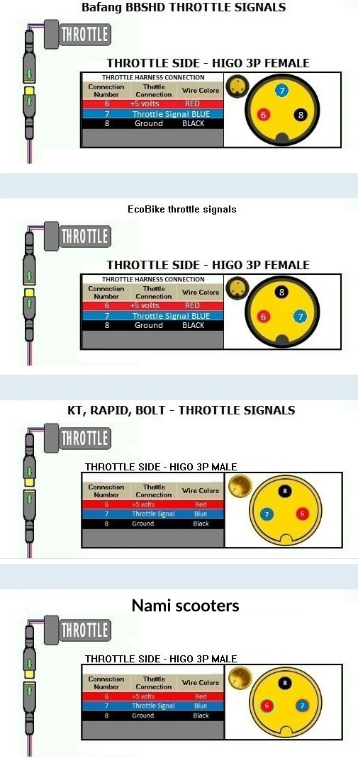
Note: The wiring diagram above is for the MALE pin connector/controller side. The FEMALE side, or throttle side of the connector looks like the top one shown in the pic below. This shows that the pins are reversed on either side of the notch because of how they are connected and mirrored...


kart_throttle_pinout_differences.png


To be 
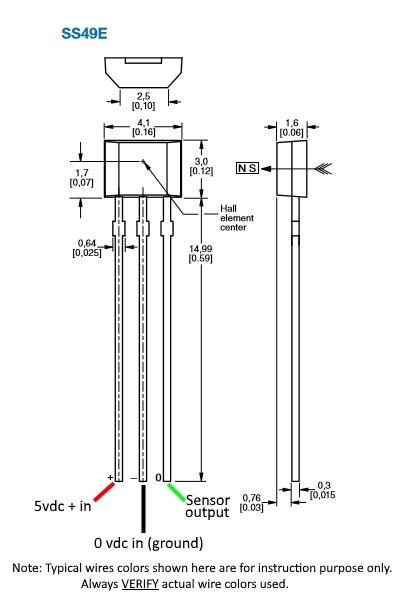
absolutely sure... things are going to where they need to be. Open the throttle and measure voltages at the hall sensors' legs... correct designations are shown in next pic...
I'd recommend doing the voltage checks with the signal output disconnected from the vesc. ;)


gXMVqVm.jpg


See that the magnet(s) are in the correct position. (May be one or two...) And verify that the battery's ground is getting all the way to the middle leg.
A bad ground will cause the hall signal output to stick wide open.

With the hall sensor removed from any magnetic gauss, the voltage output signal will be half the input voltage.
If needed, It should work just as well with the lower 3.3vdc supply. With the output being reduced by ~ .6vdc

For more information on hall sensor throttles, including different output voltage results at lower input voltages, paw thru this thread...

Guide to Hall Sensor Throttle operation, testing, and modification.

Fingers crossed that it's not toast yet.


Regards,
T.C.
 
If it's hall based and made in China, it's probably also not categorically "good". Most of the typical twist throttles from China are floppy and loose and cheap feeling. If you want a thumb throttle that I think is pretty nice and yet inexpensive the Wuxing thumb throttle is my go to...until I find something I like more. Anything in a full or half grip throttle, I invariably modify them to make them smooth and secure feeling in my hand.

 
Redundancy so you don't get a runaway throttle from a failing sensor. I think it's the standard setup on modern vehicles.

This is just my opinion from messing with many halls and not actual testing for anything that Surron claims or what you post.

I don't think it will help except if one of the 2 halls simply drops dead as an open. In a shorted hall situation (run away throttle), another hall in parallel with it probably will quickly burn out. Most halls can sink or source 10-20mA...that's hardly enough to drive a small LED! One hall shorted to 5v and the other still working and "trying to pull down" the 5v rail is unlikely to last more than seconds! It won't help throttle sensitivity either. Whatever small voltage difference there might be between them will sort of average together. I doubt that will improve "sensativity" even slightly. I think this is a marketing gimmik more than anything else. Surron owners tend to buy based on what they can brag about and not what is actually good! Just look at all the idiots bragging about their KO Moto garbage for proof of this! Linear halls are very inexpensive even from sources like Mouser or Digikey. The cost for a dual hall throttle should be maybe $3 more than a single hall throttle!
 
Last edited:
Yes I converted the pin layout for the female side. It's toast for sure now since I broke a leg off it pulling it out of the throttle :poop: The throttle looks as if it uses a long magnetic strip not individual magnets.

Hall throttles usually have a curved bar magnet polarized on the ends in them.

Using the Honeywell 49E datasheet for what I say below:

Source output current = 1.5mA (minuscule current)
No magnet present = 2.5v
Full south pole = .95v or "off"
Full north pole = 4v or WOT

Off is the full south pole or about .95v. Mid point in the magnet where north and south poles cancel out is mid point in the hall throttle output voltage or about 2.5v. You will get this voltage with no magnet present as well. WOT is the full north magnet pole or about 4v. Your hall will vary somewhat.

Note 1: Linear halls are not all the same. Some work opposite of the 49E. Many work similarly to the 49E or are Chinese knock-offs.
Note 2: Any tiny amount of loading on the hall will kill it. 1.5mA is enough to power a very small LED. Controllers have high impedance inputs for throttles so they don't load the linear halls.
Note 3: Buy legit Honeywell halls from legit sources like Mouser or Digikey. You will eventually thank me for this.
 
Last edited:
If it's hall based and made in China, it's probably also not categorically "good". Most of the typical twist throttles from China are floppy and loose and cheap feeling. If you want a thumb throttle that I think is pretty nice and yet inexpensive the Wuxing thumb throttle is my go to...until I find something I like more. Anything in a full or half grip throttle, I invariably modify them to make them smooth and secure feeling in my hand.

Not looking for a thumb throttle and this one felt relatively good.
 
I think this is a marketing gimmik more than anything else.
Dual hall effect is standard automotive practice. Don't know about Surron but automotive don't run in parallel, they run in opposing values and the controller needs to see both inputs. If one goes bad it can't cause runaway throttle because the other one isn't signalling full throttle.
 
That's typically correct. The halls in dual-hall throttles have separate signal outputs. The controllers that use them have two separate signal inputs. If the relative voltage of the hall outputs don't match what the controller expects, the controller will shutdown with whatever it's equivalent of throttle fault is.

The best way to implement such a dual throttle is to have one of the halls start at it's max voltage, and the other start at min, at throttle off position. They will read opposite of this at full throttle position, and will be about equal at mid throttle position (they *will* be equal at some crossover point, but only at that point).

If either signal fails to change the controller faults.
 
Pretty sure it was toasted anyway. Wondering if there is any way to test a throttle pin out without applying voltage to it, besides taking it apart and looking at the wires?
Not that I know of, other than pin to pin resistance (or capacitance) testing if you already know the resistances expected for whatever hall sensor was actually used in it.

There are "component testers" that use this method to attempt to identify unknown components; I've never used one so no idea how accurate they might be.

Generic listing search for them at amazon:
 
That's typically correct. The halls in dual-hall throttles have separate signal outputs. The controllers that use them have two separate signal inputs. If the relative voltage of the hall outputs don't match what the controller expects, the controller will shutdown with whatever it's equivalent of throttle fault is.

The best way to implement such a dual throttle is to have one of the halls start at it's max voltage, and the other start at min, at throttle off position. They will read opposite of this at full throttle position, and will be about equal at mid throttle position (they *will* be equal at some crossover point, but only at that point).

If either signal fails to change the controller faults.
Sure...except the Surron throttle with dual halls only has 3 wires so they are 100% in parallel.
 
Back
Top