• Howdy! we're looking for donations to finish custom knowledgebase software for this forum. Please see our Funding drive thread

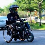
Wheelchair with Handcycle

spdas said:
To me the chart would be meaningful it they had another column showing 1 pounds of load requiring x amps, and producing y rpm,, then 2 pounds load requiring 3x amps, 4y rpm etc.
This chart is the test data from a dyno pull and shows the raw motor performance data. The 'lbs thrust' information you are requesting can be derived but also reflects characteristics of the vehicle controller, drive system, and wheel - not the motor alone.

For the test, the motor is rigged to a braking device and to a controller that has enough capacity to not introduce any limiting. The motor is spun up with no load (max rpm) and the brake applied to progressively load the motor. The Nm column shows the torque developed due to braking, the other columns show the resulting rpm, current draw, etc under increasing load. As the braking torque increases, the rpm drops and the current goes up. The reported efficiency in these charts is difference between the electrical power in (V x A) and mechanical power out (torque x rpm). Physics - not a lot of room for interpretation...

From this 'motor only' data you can apply any wheel size and gearing you want to calculate the lbs thrust and resultant speed for no-controller-limited operation. From a vehicle perspective, however, the controller actually introduces limiting under load which causes the available mechanical power to be artificially constrained as the input power is curtailed by the controller. This diverges from what the chart indicates.

If you plot this data for a particular wheel size with speed on the X-axis (from the rpm and wheel size), you will get the more familiar plot that you see in the ebikes.ca simulator (without any controller effects - as if you specified an 1000A controller).

So - the chart shows the raw motor performance without consideration for other vehicle design factors. If you want to know the lbs-thrust at some particular rpm and current, you need to do some math and consider all the other parts of your vehicle - not just the motor.
 
Question, IF my full charge voltage is 54.6, and I'm not supposed to full charge,(for storage) What is 80% ? 54.6x .80= 43.7 ?? my LVC is 44. Or 54.6-44=10.6 x .80= 8.5 , 8.5+44=52.5. Is that it?? My EBK owners manual says to charge my battery ASAP after riding. I assumed it meant charge it up! Have I been drinking the Allcell coolaid all summer? the bike is sitting now Since last Saturday topped off for this weekends ride.
 
It would be 80% of amp-hour capacity not 80% of voltage. For lithium there is very little amperage increase at the top of the charge and very little amperage loss at the bottom of the charge with voltage dropping or increasing rapidly. For example a "3.3 volt" cell is basically dead at 3 volts and degrades very rapidly under 3v and fully charged at 3.45 volts and increases to 3.65v or more very rapidly, with very little amperage added. ---that takes 90% of the amperage capacity between 3v and 3.4v or even most of the charge between 3.25v and 3.35v. A different situation for lead cells, as they can be charged higher because they can equalize by "blowing off steam", but not with lithium.

francis
 
Q100H 201rpm works as a charm at 75V, but some 6-fet controllers have HVC (High Voltage Cutoff) and few other 50V components inside that must be modified to in order to enjoy it. Otherwise it will simply refuse to turn the wheel more than half a turn.

You really have to keep the current down, forces at 75V are brutal at standstill and chances are your Q100H clutch will simply slip making funny noises. 1kW is the practical limit with reinforced clutch springs, a bit less with default clutch springs.
 
Aloha, all.
I am working on my build now and need some thoughts about achieving the speed and power that I want. Since I am making a "driving pod" for my wheelchair and not your every day bicycle (as pictured below) I will explain where I am now and maybe you can direct me:

1) I have the Q100h motor laced up to my 16" rim as an experiment to see what the "real world" performance will be.

2) I need to use 16" or smaller rim as I need the rig to fit into tight spaces and be highly manueverable.

3) I have been emailing with Leaf and Peter there suggests the 14" rim 1000w and they will make it into a 730 RPM motor @48 volts. Or they can do a 560 rpm.
I am looking for a solid 20mph with up to 25mph on occasion. I have no hills and my usual jaunts are 5 mile round trip to Costco or Home Depot. I really do not need a lot more starting torque as the driving pod already "burns out" with my 36v 250watt 12" wheel

4) I am going to play with some 9ah 12v leadies and I can put or add 12v to 48 or 60 on experiment as it is soo easy to add or subtract a battery.

5) the question is about torque. I hear mixed feelings on this board about higher RPM sacrificing Torque. Given the above info should this lose of torque be so much of a concern to me?

After I get knowledge about what my Q100h will perform with varying voltages and CA adjusting the amperage, I should be able to gain some knowledge on how to proceed on how to build a more perminent setup.

Thoughts?

thanks
Francis
 

Attachments

  • sherpa.jpg
    sherpa.jpg
    55.4 KB · Views: 1,947
Aloha, Just thinking out at the keyboard.

What do you think about the Dewalt 20 LION 4 ah batteries. (or the 5ah when they come down in price? Using 3 for 60v and even 6 for 8ah and 60 v?

1) Cheap enough on Ebay @ $44.00 each and with a warranty! Or may even wait for Home Depot to have a super Christmas sale.

Experiences? can they power/discharge quickly enough? I use several tools here at the shop that uses these 20v 4ah batteries and they get charged 3-4 times a day 6 days a week and LAST, also I assume they are BMS conrolled


what do you think?

francis
 
From what I read about the Q100h it has 30% more torque then the original Q100.
I was unable to find it on the motor sim on ebike.ca to check lbs of torque.
My understand of wheelchair having a quickie triumph is we have very little rolling resistance. The hub motor you have is a 12:6 gear ratio.
I do not believe you will have an issue with not having enough torque to get moving if that is your concern with the Q100h.
Plus you are putting it on a 16" rim most website has that motor on a 24-26" rim so I do not believe you would have an issue with torque maybe you will lose speed if you put it on such a small wheel.
If most kit are with 24" rim @ 36v with stock speed of 20mph then you might lose a few mph going to 16" rim.
 
My experience with power tool battery are not that good.
Recently I build a all motor recumbent trike 6t mxus running @ 49v on a 17" moped rim.
The speed I was getting was a bit undesirable @ 18mph.
Then Hobbyking had a cyber deal on 4s hk hard case lipos. I purhcase enough to get me to 90v with my current 49v hk lipo setup.
While waiting for the battery to come in from the west coast I couldn't wait to see what they would do.
So I string some 18volt dewalt battery I had togther to see what speed I would get running @ 90v.
18v + 18v + 49v lipo = 85v
I hit 28mph but the voltage drop was really bad from 85v down to 75v and I was only able to get a few mins of run time before the 2 18v pack died.
 
Simonvtr said:
My experience with power tool battery are not that good.
Recently I build a all motor recumbent trike 6t mxus running @ 49v on a 17" moped rim.
The speed I was getting was a bit undesirable @ 18mph.
Then Hobbyking had a cyber deal on 4s hk hard case lipos. I purhcase enough to get me to 90v with my current 49v hk lipo setup.
While waiting for the battery to come in from the west coast I couldn't wait to see what they would do.
So I string some 18volt dewalt battery I had togther to see what speed I would get running @ 90v.
18v + 18v + 49v lipo = 85v
I hit 28mph but the voltage drop was really bad from 85v down to 75v and I was only able to get a few mins of run time before the 2 18v pack died.

What was the AH rating of the 49v Lipo
and what was the AH rating of the 18v dewalts?

thanks francis
 
Simonvtr said:
From what I read about the Q100h it has 30% more torque then the original Q100.
I was unable to find it on the motor sim on ebike.ca to check lbs of torque.
My understand of wheelchair having a quickie triumph is we have very little rolling resistance. The hub motor you have is a 12:6 gear ratio.
I do not believe you will have an issue with not having enough torque to get moving if that is your concern with the Q100h.
Plus you are putting it on a 16" rim most website has that motor on a 24-26" rim so I do not believe you would have an issue with torque maybe you will lose speed if you put it on such a small wheel.
If most kit are with 24" rim @ 36v with stock speed of 20mph then you might lose a few mph going to 16" rim.


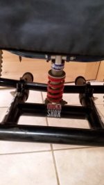
thanks, I am even looking at a 14 rim/motor mag as I want it highly manuverable in tight spaces. I have front springs on my front driving pod from a BMX bike. I also bought a XRT Quickie wheelchair with the mono-shock and wide tires to help cushion when going 20-25. So on with the experiment.

francis
 

Attachments

  • s-l500.jpg
    s-l500.jpg
    18.3 KB · Views: 1,931
  • s-l64(3).jpg
    s-l64(3).jpg
    1.3 KB · Views: 1,931
With identical gearing and wheel size the same motor wound to a higher rpm/volt will have less torque per amp, but is capable of the same torque since it's copper is thicker and can handle more current for the same heat generated.

If you're already having traction issues, then the higher rpm version is what you want, since with the same controller and battery it will be smoother. It will also be capable of more speed, which is nice even if you don't use it, since you can maintain your speed up gradual inclines or into headwinds. Plus it gives you better acceleration through the mid-range.
 
I believe the traction issue is more with the balance of the wheelchair. Most of the weight of the rider is on the 2 rear wheels so adding a motor that extend future out in the front reduce the traction that front motor has. There are wheelchairs that allow you to move the pivot point of the axle forward or future back to change the weight of the wheelchair, but then if you move the axle back to put more weight to the front then when you are not using the motor to get around it would make it very hard to do wheelies and the ride would be very bumpy due to the front caster wheels taking most of the weight. It also would move the rear wheel back more which is not the ideal position for each push of your hand.
 
spdas said:
Is not VxA=Watts? then why do I see ads on ebay for controllers 48v with 25 amps equaling 350 watts?

thanks
francis
Controller V & A ratings are motor input watts ...
Motor rated watts are motor output watts. Motors are rated for output and at a specified voltage. EG 24V 500w motor and 36V 750w motor are often the same motor.
With sufficient input amps, any motor will full throttle input 700w to output 350w at 40-50% of no load speed.
Lower speed full throttle can draw much more than 1000w while outputting much less than 350w.

A 48v 350w output motor could be paired with a 48V 25A controller ...
But motor must use heavy windings to survive prolonged full throttle at low speeds.
Such a combo would exhibit excellent "off the line" acceleration ... thus spending little time at high drain low speed.
 
sherpa.jpg
Aloha. I have searched here and googled and got basic understanding of the motor/controller hookup, but can you help with these questions?
I bought a few months ago the Q100h motor and S06P controller.

1) as you see in the pic, my wheelchair driving pod is a bit "different" to a bicycle, so can I just leave the PAS empty?

2) Do I need to use the brake wire? What is the hi and low brake?

3) I guess the LCD/LED wire on the controller is for the display, which I do not have yet, but can it run with out it?

4) What is the speed sensor wire for?

5) I figured the green,blue, yellow (phase) and the black, red battery,
but what are the blue, yellow, red, green, black wires coming out of the motor and do I need to just solder them to ones coming out of the controller?
6) I assume the hand throttle red/black/blue just connect to the controller
 
1) PAS not required.
2) You don't need to use brake wire. However you should remove the blue loop, this is cruise loop and will turn on cruise when you hold a constant throttle. Without brake wire you will have to blip the throttle to turn cruise off or switch the loop with a momentary switch to keep cruise. Brake wire is still highly recommended in case you accidentally stick throttle when braking.

3)You need to set up the controller to match your motor parameter... So unless you fluke out on its default settings, then you need it for setup. Not 100% on this never tried it, theory only, but you can then run without LCD by grounding out the controller lock wire on the LCD connector. I don't know the color code of your pinouts so you will have to figure which is the lock on LCD connector (there should be Tx, Rx,v+,gnd, and lock out).

4)Speed sensor to show your speed and to keep LCD on. Not required(in theory) if you are running without LCD and keeping controller on with the bypass in 3)

5)6) you are correct. Smaller wires from motor are hall sensors, it helps controller know motor rotor position for smoother startup and efficient operation. You should use them.
 
Safety and common sense dictate that yes the ebrake is always a build requirement, because it gives you a way to cut motor power in the event of a runaway condition. eg a simple throttle failure. Whether it goes to the brake handle or a button on the handlebars isn't important. Low is activation with a short to ground. High is commonly used on systems with brake lights, so sending any positive voltage from about 9V up to pack voltage to activate the ebrake that way. On escooters they usually tie into the brake light circuit, so when the brake light comes on it cuts controller power to the motor.

Don't permanently solder the hall wires until you prove the YGB (Yellow/Green/Blue) combination is correct. It's not standardized between manufacturers, so use only short pulses of throttle with the wheel off the ground when checking that the wiring is all good and the motor starts up quietly and the motor spins in the proper direction.


Thanks everyone. that explains a lot. I could not find a wiring color diagram for the Q100h motor, but included the diagram for the controller S06P along with a pix of the wire out colors for the motor. Can you direct me to which of the 5 color wires go where on the controller? If hard to see in the pix, the colors go from the top, red,green,black,blue, yellow.

thanks
Francis
 
Aloha, here is my build so far. Q100h, kelly or S06P controller, 36v to 60v 9ah lead (for experiment to see what the S06P will stand, hydraulic disc and wheelchair is Mono-Shock suspension and 24x2.1 tires, front forks are off an old BMX with springs and CA3 analyst. The rest of the frame is bent from EMT I have 2x36v Lipo, but easier to play around with Lead to change the voltage. Merry Christmas.
 

Attachments

  • mybuild.jpg
    mybuild.jpg
    223.3 KB · Views: 2,349
Aloha, I cannot figure how to hook the motor to controller;

1) Q100 motor 3 phase motor wire, obvious where it goes on the controller

But the 5 small wires where do they go on the s06p controller? The only location that seems possible is the same-color LCD/LED wire, but that cannot be right!

here is the diagram. To test I only have the power and throttle hooked up.
 

Attachments

  • wireingcontrollersmaller.jpg
    wireingcontrollersmaller.jpg
    127.1 KB · Views: 1,979
Do you think that is a sensorless controller? In which case you can use the throttle now and motor should spin.

Else, that white connector looks like the one but the wiring diagram shows something else.

Use a multimeter and see if there is a 4.3 to 5V signal between ground and red on any connectors with 5 pins (2 pins for power, 3 pins signal).

I'm gonna say its a sensorless controller though.
You should actually open it up to be certain. .. Then it can be identified whether the board has hall inputs.
 
So let me step out into my grey-knowledge area.

I guess the S06P is a sensorless controller and the Q100h has a hall hookup.

When the battery is hooked up, should I not be getting 5v at the various plugs that have the black and red? I'm not
But my CA3 works fine

So I assume I am NOT "turning on the Controller?"

On the s06P wiring, I shorted the #1-2 and #3-5 pins since I do not have a LCD/LED

Suggestions ???

****thanks Skedgy Sky, I posted before I saw your post and it seems we are at the same conclusion. The controller has no power going to the + - on the various plugs****
now what?
 
Continuing my problem, I do not have 5v on any of the connectors.

I have the S06P controller hooked up to 36v,

Should I not see 5v at any plug or do I need a PAS or Speed sensor or some other connection to wake-up the controller?


thanks Francis
 
Merry Christmas. I am still trying to get my new S06P Controller to activate and since I am such a nooby,
I cannot tell if I am doing something wrong or is the controller dead?

I get a crackle when I hookup the 36v, so I guess that are the cap's charging up, but I get NO 5v at any of the plugs.
I have the diagram that shows 1,2 and 3,5 pins on the LCD wire need to be connected if I do not have a LCD.

So is the controller dead or not hooked up correct?

Anyone?
 
-------------------------------------------------------------------------------------------------------------------------------------------

Edit: i have read a bit about the controller on some german forums and i might know what the problem is.

on the lcd plug (1)red cable should read your battery voltage if not just connect the blue wire(2) directly to the positive terminal of the battery and black(3) to yellow(5).
 
Back
Top