SwampDonkey said:
The new throttle is a standard Cyclone 6 wire. Its the second one I pictured.
The
second one you pictured has
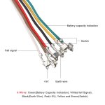
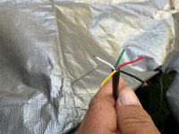
5 wires, and is labeled as follows...
red +5 volts power cable.
black negative power cable.
green signal.
yellow power positive.
blue power positive or electric switch.
From your description below, this seems like the wiring you are using..??? As with the 6 wire descriptions, the throttle would not work... Please confirm.
SwampDonkey said:
So what about the orange and brown wires? Based on what I read here I connected green-green, black-black, and red-white. The bike motor came on, but the key switch, display, and throttle didnt work. The motor just went full throttle.
Bad ground (black) wire connection?
SwampDonkey said:
Edit:
I have the throttle working, BUT the key isnt shutting it off. The display goes black when the key is turned, but the throttle still operates.
I have:
Black -> Black
green -> green
red- > white
orange -> yellow
brown -> blue
This is actually the same issue that led me to replace the old throttle. How can this thing still work with the switch off? Is it just wired wrong?
From your description, the throttle's yellow wire is being supplied full battery power from the orange controller wire.
When the key is turned on, full battery power is
switched to the display input. (thinking your talking about a voltage LCD display on the throttle housing) And
also to the blue wire. (please verify this)
If your controller has an ignition circuit that requires full battery power to energize it's electronics (which would have to be bypassed at this time). The blue wire would connect to that wire. Do you know where the brown controller wire goes? Or what it's suppose to do? Information about your controller and it's display may be helpful.
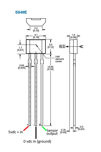
Great to hear your throttle's hall sensor made it!