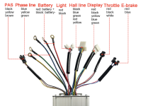
Wiring KT Controller 50A julet waterproof

kikomania1

1 µW
Joined
Jan 2, 2022
Messages
4
Hello,

I'm upgrading my KT controller from 25A:
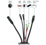
old.png

to use 50A model instead:

schema1.png

The wires are different and all the wires in my bike are julet, so I have to adapt them.

There are two special considerations:

- The 9 pins motors = motor phase lines (3 wires) + motor hall lines (5 wires), but I don't know in which position related with the 9 pins connector.
- The 1 to 5 Cable = e-brakes x2 (6 wires) + throttle (3 wires) + display (5 wires) + front light (2 wires). Again, I didn't find a schema to know how they should be fit.


It's my first time doing this, and I feel so close and yet so far. Any idea/suggestion of what I can do to pair them correctly?
 
Last edited:
I'd open up your old controller and measure where each wire on the board inside goes to on it's respective connector pin, and write those down for each pin and each wire for reference.

If the wires on your new controller are marked the same on it's board inside, you can transplant the connectors/cables from the old controller to the new one, replacing the entire new harness with the entire old one, to make things "easy". If they're not marked the same then you'd need more verification before doing this.

But that's where I'd start if I was doing this. taking good clear direct-sunlight-lit pics of everything in every step as I go, and documenting it all, so it could be undone if necessary, or making it easier to troubleshoot later.


FWIW, there are diagrams out there of the common pin connection order for most of these Julet and Higo connectors, some of which can be found in image searches like this:
etc

and on ebikes.ca's connectors page
 
Or you can keep the existing wiring and cut off the ends. Use a kit similar to….

QLOUNI 560pcs 2.54mm Pitch 2 3 4... Amazon.com

…..to make your own ends. Then you don’t need to solder to the PCB. Like Amberwolf says, though, document, test, and compare all leads. You can trace leads to the PCB for identity. Take lots of pictures.

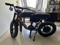
I was thinking something in that way: If I allocate the new controller properly in my bike, I actually don't need 1-to-5 julet

IMG_6641.jpg

Just cutting and making waterproof connectors in the new controller wires will be made the magic.

The cons are motor wire it's going to be longer, probably not good idea for temps?

Still 1-to-5 julet can give me more option, but It seems it will be need more investigation work to make it possible.
 
Last edited:
Hello, I'm finally doing this. However, it seems there is some incompatibility between the controller (kt48svprk-ff01l) and the display (lcd8h).

Although the wires are the same colors, the button for turning on the display turns off if I release the button. Also, the voltage in the display is reported wrongly. I suspect this is some low-voltage protection, but it's unsure what I can do to fix it.

Maybe this display is newer than the firmware running in the controller. I don't, I'm desperate ☹️
 
Short answer, if your motor and peripherals want Julet plugs, get a controller with Julet plugs.

Nuanced answer, if your motor has a typical 9 pin plug on it, you'll cook the wires by using a 50A controller, unless you limit it electronically. Those are good for 25A in my experience, though some sellers will go to 30A. I prefer to use them with 22A controllers so I don't have problems.
 
That's pretty far away from the current problem 🙂 I started doing this because the motor is 1500W, and the most powerful KT controller with Juliet waterproof wires is 25A, so the motor is far from it's power peak. Although your assumption is right, you can always change the motor wires. I'm missing something.
 
Well, if you want to use 50A, you'll need to remove the 9 pin plug and address the wires with heftier connectors. I find 14ga motor phase wires adequate for 60A if they're short, but 16ga not adequate. But okay for 40A.

Use thicker conductors for the cable that connects battery to controller, and controller to motor.
 
Back
Top