OK, so the first of the XLD controllers arrived (the smaller one, from Amazon:
https://www.amazon.ca/gp/product/B07DQJJV46/ref=od_aui_detailpages00?ie=UTF8&psc=1).
Gotta say, for $40 (Canadian), it seems put together better than expected, though the bar was low. Upon seeing this thing in person, and revisiting this thread, it occurs to me that variants of this thing - at least units that seem to run with the same unique MCU - have been discussed on ES for some years. I haven't worked my way through all of the threads yet, but this is flavour I now have in hand. It doesn't have the hookup for the external LCD, so I'm not sure how radically different it is at its core.
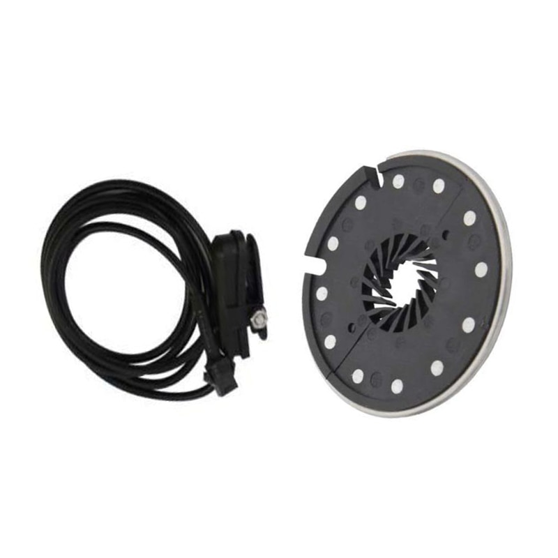
View attachment 7
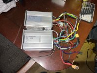
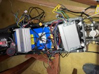
Wiring:
View attachment 6
PCB:
View attachment 5
View attachment 242328
View attachment 242332
After changing out a lot of the connectors for something I can actually attach to a bike (Andersons and JSTs), it did install painlessly. The auto-learn feature for the phase/hall wiring worked well (you connect together the green wires, power up the bike, and it starts spinning the wheel. If it's spinning the wrong way, you touch the throttle and it reverses - disconnect the green wires, and this setting is remembered). There is a speed connector on there that does the expected. There are three speed settings - leave the connector open, and the motor runs to the middle setting. Short black to grey, and the top speed is reduced. Short black to white, and you get 100%.
There is a pair of grey wires whose function is claimed to be "EBS". These come connected together out-of-the-box. Sure enough, if you apply the brake (I have it wired to the "brake low" input), the motor is slowed down to a complete stop. My suspicion is that this isn't actually doing any regen - it's just shorting the phase wires to get the braking effect. I won't be able to prove this until I try the controller out on a bike with a Cycle Analyst on it.
Now - there *is* the often found tie between the EBS (or regen, if true) function and LVC. This controller claims to be a "36/48V" unit, and to auto-detect its power source. When I have the controller connected to a 10S lithium pack (whose state of charge was at around 39V when I was testing), the EBS feature works as expected. If I connect my usual 12S pack (which was hot off the charger and running at 49.9V), the EBS feature DOES NOT work.
Studying the PCB, there is an interesting resistor array that appears to be in parallel with one of the resistors that form what I'm assuming is part of the voltage divider that is feeding the LVC measurement to the MCU.
View attachment 2
Any of these resistors can be jumpered to GND to change the balance of the voltage divider. It's interesting that the options go all the way up to 80V. The board is not populated with components that would allow you to even think about going there. The caps are 63V units, and these are the FETs that come with this thing:
View attachment 242336
Those are 68V parts.
For giggles, I jumpered the "60V" resistor in the LVC array, and now EBS (or regen, if true) works with the 12S pack. The bike won't run, however, with the 10S pack - evidently, the LVC *has* moved up, well above 39V - I need to go back at this with a variable power supply to determine what the real cut-off values are. At least, if none of them are satisfactory, there's a clean place on the board to play with different resistor values
")
.
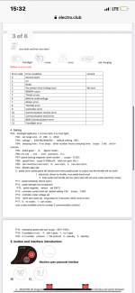
Anyways, I thought I toss this out there - the markings (and chip used) on this board seem to be very similar to the board posted earlier in the thread. I've mapped out where all of the coloured wires go, and what the do (though I have no idea how the "alarm" feature is used), so FWIW - this is the diagram:
The "power and electric lock" function is straightforward. The heavy red and black are your main battery power, and the orange wire is the "ignition" which provides battery power to the actual controller logic.
Phase and hall wires are standard, as well. There's a group of pads on the PCB - "5V", "U", "V", "W", and "GND" all together. These are the red, yellow, green, white, and black hall wires, respectively.
The EBS brake wires are both grey and, when jumpered together, turn on the braking (or regen, if true) capability - provided the LVC and power source are compatible. These are connected to pads labelled "DS" and "X" on the PCB
The "high potential brake" (it's purple) is an input signal that would be used if this controller were used on a scooter. You'd connect this to the same 12V signal that drives the bike's tail light. It goes to "SH" on the PCB and has the same effect as shorting the low potential brake.
The low "low potential" brake (the one most of us actually use) is a black and white, going to "GND" and "SL", respectively. When shorted, this switches off motor power and activates EBS.
The throttle ("handle accelerator", as diagrammed) is red, white, and black. Red goes to "+4.3V", black to "GND", and white to "SD" - the latter being the actual throttle signal.
The "gear switch" is the 3-speed control. Black goes to "GND", grey to "K1", and white to "K2". Left open, the motor runs at its "medium" speed. Short black to grey, and speed is reduced to "low". Short black to white and you get full speed.
The "reverse function" (brown and black, going "DC" and "GND", respectively) reverses the motor when shorted.
The "cruise function" (blue and black, going to "Q" and "GND", respectively) holds your current speed when shorted.
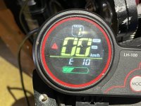
The "autometer signal" is interesting. It seems analogue (though probably just buffered PWM). The faster you go, the more voltage you read on this line. What's weird is that it hangs out of the controller, unprotected and uninsulated, but ramps up as high as 18V when the bike is at full throttle on a 39V pack. It's blue, and connected to "S+". I have no idea how I'd use this, though driving a regular analogue panel meter could be fun.
There are two connectors for an alarm function - which I have NO idea about.
Alarm power (red and black) goes to pads marked "PS+" and "GND".
Alarm signal is three wires - Grey goes to "A3", white goes to "W", and orange just brings back out full battery voltage (it's directly connected to the orange "ignition" wire).
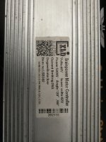
Dunno if any of this is useful, but its the first time I've had my mitts on one of these "X806M" based controllers.
I'm dubious about the "sine wave" output of this thing. So far, the motor I'm playing with sounds exactly the same as it did with the older model Infineon job that was previously on there.