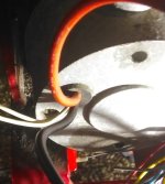
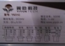
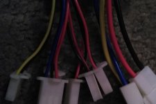
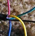
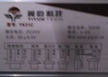
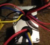
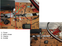
Thank you very much..I am almost positive I have it hooked up correctly....one more question,, ,, I have a I have a red, green and a yellow...which one off them connects to the motor itself...which one is positive and which one is negative,,and can two of them be tied in together.... :Thank you again for you kos
You are using an out of date browser. It may not display this or other websites correctly.
You should upgrade or use an alternative browser.
You should upgrade or use an alternative browser.
XLD Brainpower motor controller XunLiDa
- Thread starter pavlik1
- Start date
dduett said:I have a I have a red, green and a yellow...which one off them connects to the motor itself...which one is positive and which one is negative,,and can two of them be tied in together....
You'd have to show, on that wiring diagram you posted, which specific wires you're asking about.
In general, for the motor, it has three thick wires (phase), green, yellow, blue; these connect to the same ones on the controller. If the motor only has two thick wires, it is a brushed motor and cannot be used with this controller.
It may also have 5 thin wires for the hall sensors, red, black, green, yellow, blue, and possibly one other of whatever color (often white) that is a speed sensor. Not all motors have the thin wires. these connect to the same ones on the controller.
For positive and negative on the controller to the battery, refer to the diagram you posted, and whatever your battery shows (usually red is positive and black is negative, but this is not always true, and a wrong connection can seriously damage or destroy either or both parts).
Yeah, that's almost certainly a brushed motor. You'll need a brushed controller to operate it; the one you have now won't be able to. They're pretty cheap, but you do need to get one with a current limit that matches your motor.
At a guess, that motor is probably a couple hundred watts or less, based on wire size vs motor size, and what I can see of the frame (kick scooter?). Probably a Unite brand. They don't last long if you use more power than they were made for. It should have a label that tells you what it is.
If it's a 24v system, at say 200w, then 200 / 24 is about 8A max for the controller current limit. Higher than that, and under load the motor will pull more power than it can handle and overheat, and burn out.
You could also change the motor out and use the controlelr you have, but that's more expensive and likely means building new motor mounts, possibly modifying the frame, etc.
At this point, I think you need to post *complete* details of your entire project, including pics of whatever it is the motor is on, and *everything* you know about it, and exactly what you want it to do, under what conditions, including wind, terrain, weights, etc etc.
Without that, we're just going to end up dragging this all out for pages and pages with one tidbit at a time, as new problems crop up because of info we don't have to help us help you do what you want.
Or else you'll get it working, but be disappointed with it, and end up having to start over again. Or blow something up or burn it out, and end up replacing everything one bit at a time.
UnicycleSanta
1 µW
- Joined
- Jul 27, 2019
- Messages
- 3
Good afternoon everyone,
I have a Brainpower motor controller with LCD (LH-100) all wired up and I am getting an error code E10 as well as no throttle power. I have tried everything and the internet has not served me well in finding a result.
I have a Brainpower motor controller with LCD (LH-100) all wired up and I am getting an error code E10 as well as no throttle power. I have tried everything and the internet has not served me well in finding a result.
Did the system ever work, or is this the first test?
I don't know where a manual can be found for it, but Xunlida appears to be the manufacturer. There is a thread
https://endless-sphere.com/forums/viewtopic.php?f=2&t=96736
about this controller series that reports some info, but doens't mention the specific code you're getting.
I don't know where a manual can be found for it, but Xunlida appears to be the manufacturer. There is a thread
https://endless-sphere.com/forums/viewtopic.php?f=2&t=96736
about this controller series that reports some info, but doens't mention the specific code you're getting.
UnicycleSanta
1 µW
- Joined
- Jul 27, 2019
- Messages
- 3
This is the first test, I wonder if I should get a replacement unit and test it out.
UnicycleSanta
1 µW
- Joined
- Jul 27, 2019
- Messages
- 3
Hey everyone, I have been working on a project and am hoping you can help. I am wiring up a XLD controller and started with the 350w, but the low end torque was just not there. Since then I switched over to a 1000w unit and the low end torque is back. The problem I am running into is my plan was to take the display from this kit:
https://www.amazon.com/gp/product/B07MDWZBHR/ref=ppx_yo_dt_b_asin_title_o00_s00?ie=UTF8&psc=1
And open up the controller to see how the display was connected to the board. From what I can see, the White hall wire goes to F3 pin, with a 0.1 K 100 cap going from the F3 pin to ground. I assume this is the wheel speed sensor. Then there is a 36v Red wire going from the display straight to battery power (for on/off as well as battery level). There is a blue wire going from the display to contact F4 and a green wire going to contact F5. Finally there is a ground wire. I wired all of this into the 1000w controller and the display turns on/off the scooter, reads battery level, and controls the lights, however I have no throttle/speedometer and get an E10 error.
I know I am doing something that isn't necessarily common, however that is all the fun of this hobby. If anyone has knowledge of the workings of these boards or a full schematic with contact identities that would help a bunch. I am positive that this is possible as the dash setup only needs to act as a control interface, and the XLD boards all have the same main chip as well as the same contact points on the boards. The only difference between LCD/non LCD or wattage is which contacts are utilized or how many mosfets there are. Of course there are also different caps and resistors for the increase power load but the point is the control interface should still be compatible.
You've given some very essential detail in this thread that you didn't give in the other one, that would've helped us help you solve (or at lleast identify) the problem more quickly. :/
The LCD displays from one brand/model of controller are generally not compatible with a different one, becuase they use different "languages" to talk over the serial lines. Even between different models of the same brand, they may not work.
Sometimes they also use different electrical signals, which can damage the hardware, but that's rarer, and I ahven't seen that within the same brand.
So if you want an LCD on your controller, you should use the one that came in it's kit, or use the controller taht came with the LCD, etc. Or else order an LCD from the manufacturer (or a seller) of the same brand and model controller you're using, or vice-versa. (that's difficult, becuase most of the time they dont' seem to understand which stuff you have, and which you want, or else they simply don't have what you want but they'll sell you something anyway. )
If they don't match, they wont' work, with few exceptions.
Even if you see the same name on one vs the other--internally they're different, in the software/firmware. For instance, I've seen what look like identical Kingmeter displays on my old Fusin kit with a LiShui controller, and several Bafang systems--but mine won't work on theirs, and theirs won't work on mine. No data is displayed on either one (though they do power on). AFAIK, the controllers are all LiShui, in those instances. But they still wont' work together.
Unless you can do serial data capture from the controller that goes with that LCD display, and from that LCD to that controller, while pressing all teh button combinations, and while riding at various speeds, etc., and then do more serial data capture with the controller you want to use the LCD on, with the LCD that came with *that* controller, and then make a "translation" unit (arduino, etc) once you figure out what the data means and can make lookup tables for it, then I don't know of a way to make incompatible units work together to display useful information.
If the hardware is electrically incompatible, you'd also have to fix that (but it probably isn't).
I'm pretty sure there's at least one thread where someone at least started to try doing this, though I don't recall if they finished.
Was titled something like "display protocol", dont' recall exactly.
I think this is the most complete one
https://endless-sphere.com/forums/viewtopic.php?f=2&t=94850
it only applies to those specific items in the thread...but it shows the process you can use.
Full search:
https://endless-sphere.com/forums/search.php?keywords=protocol&terms=all&author=&sc=1&sf=titleonly&sr=topics&sk=t&sd=d&st=0&ch=300&t=0&submit=Search
I can not begin to thank you enough for your help..I was about to give up and just set my scooter outside on the road so somebody could pick it up....I'm have ordered 2 new speed controllers that will be here tomorrow,,, so hopefully that will do some good as well.....I will post tomorrow afternoon and let you know...I would love to pay you for your time and your words of wisdom....
What are the new speed controllers? (to make sure you're getting compatible ones)
Also, you didn't post the project details; if you did that we'd be able to better help you pick stuff you'd know would work.
If you really do want to contribute, I have a link in my signature you can use. I don't get much via that, but it helps pay for food for the four monsters (and sometimes bits for the trike).
Lh100Error10
1 mW
- Joined
- Jul 29, 2019
- Messages
- 14
UnicycleSanta said:Good afternoon everyone,
I have a Brainpower motor controller with LCD (LH-100) all wired up and I am getting an error code E10 as well as no throttle power. I have tried everything and the internet has not served me well in finding a result.
I installed the controller (LH-100 LCD and brainpower controller kit) yesterday and also got error 10 after turning it on, the throttle doesn't respond either.. did you find a solution?
I read online it means that either the LCD/LCD cable/controller is faulty.. or possibly wrong wire connection
I bought it from AliExpress, did you too?
Lh100Error10
1 mW
- Joined
- Jul 29, 2019
- Messages
- 14
Hey guys,
I have been struggling with this problem fpr the past two weeks, tried 2 brand new contollers but no luck.
i have brain power controller and xld16 lcd
with learn wires connected, when i turn on the motor it works fine. but when i disconnect thepeaen wires and turn it on again, by pressing throttle i just hear the engine moving but the wheel does not move. please help
docw009
10 MW
jizro said:Hey guys,
I have been struggling with this problem fpr the past two weeks, tried 2 brand new contollers but no luck.
i have brain power controller and xld16 lcd
with learn wires connected, when i turn on the motor it works fine. but when i disconnect thepeaen wires and turn it on again, by pressing throttle i just hear the engine moving but the wheel does not move. please help
You did not provide any info on the motor. Is it a geared motor? If it is a geared motor, your description suggests that the learn function spins the wheel forward. Then you disconnect the learn wires and now the motor turns backwards. And when a geared motor turns backwards, you can hear it spin, but there is a clutch that prevents it from spinning the wheel backwards.
I guess you could flip two of the phase wires after it does the learning. THen it might work. Or you could flip the wires and try to make it learn again.
Roots Rocker
10 mW
- Joined
- Dec 29, 2018
- Messages
- 24
Hello,
You have to Disconnect the Learnwires while the Motor runs in the right Direction.
mfg Martin
You have to Disconnect the Learnwires while the Motor runs in the right Direction.
mfg Martin
I am trying to wire up one of these motor controllers up too. I followed all the info here and the good news is the motor is running and running in the right direction. The bad news is the accelerator does not work at all, the motor just runs full on all the time. Checking the Chinese hand accelerator, which consists of a couple of integrated diodes, the diodes check out fine. But checking voltage on the outputs to the motor, as son as the accelerator is hooked up there is a constant 10V going to two legs of the motor, if I disconnect the accelerator no voltage goes to the motor at all. So right now I am wondering if this is a defective motor controller. Has anyone tried using a potentiometer to controller one of these things? So I can take the hand accelerator out of the loop? If so, what value potentiometer did you use? Any guidance on this would be appreciated. Richard
I found my problem ....it is the Chinese speed controller after all. One of leads on the diodes in the controller actually had a hairline crack on it ...I had to use a magnifying glass to see it. I put a 250k pot in place of the controller ...and while not optimum I could at least control the speed somewhat.
Now looking at another throttle replacement brings a question ....does that lock/ignition wire get rid of the need for a battery cutoff switch if you have a throttle with an on/off switch? Meaning, instead of wiring the lock/ignition wire to positive, you wire it to the throttle's on/off wire and now you do not need a battery cutoff switch? No worries of the battery being drained when in storage then?
Hello
I am finally back.
I try to identify the pb with your advice :
now i still have the following behaviour :
(1) When i switch on the display : throttle disconnected
i have error 7 msg on the display but the wheel can be controlled using +/- button of the display. The wheel turns in the right direction.
(2) When i switch on the display : throttle connected)
i have error 8 msg on the display but the wheel can be controlled using +/- button of the display. The wheel turns in the right direction.
The throttle doesnt work :/
If you see any pb on the picture attached - please help ! :wink:
thanks for your help.
Regards.
I am finally back.
I try to identify the pb with your advice :
- I have checked the phase motor : they are not broken few mOhms between each of them.
the circuit is open betwen phases and the "case"
now i still have the following behaviour :
(1) When i switch on the display : throttle disconnected
i have error 7 msg on the display but the wheel can be controlled using +/- button of the display. The wheel turns in the right direction.
(2) When i switch on the display : throttle connected)
i have error 8 msg on the display but the wheel can be controlled using +/- button of the display. The wheel turns in the right direction.
The throttle doesnt work :/
If you see any pb on the picture attached - please help ! :wink:
thanks for your help.
Regards.
Roots Rocker
10 mW
- Joined
- Dec 29, 2018
- Messages
- 24
Hello,
The wirecolours from your Throttle matches to the Controller Plug ?
mfg Martin
The wirecolours from your Throttle matches to the Controller Plug ?
mfg Martin
Roots Rocker said:Hello,
The wirecolours from your Throttle matches to the Controller Plug ?
mfg Martin
Hello
Yes they match.
the electrical colored flat ribbon is only a "hack" to connect male/male connector of the throttle and controller.
Similar threads
- Replies
- 19
- Views
- 1,735


