
You are using an out of date browser. It may not display this or other websites correctly.
You should upgrade or use an alternative browser.
You should upgrade or use an alternative browser.
Y-pedal's two stage RC drive..........
- Thread starter recumpence
- Start date

Ypedal
100 TW

Ypedal
100 TW
MitchJi said:Hi Y,
recumpence said:Hey, for those who want to know, I now have round tube drive clamps available in 1.5 inch and 2 inch ID sizes. Various shims can be made from basic aluminum tubing with various ID and OD combinations.
MattI think Matt said the clamps might work (I think he said he wasn't sure) with some sizes of oval tubing. If he thinks it might be possible it's probably worth a shot (all you can lose is the cost of round trip shipping).Ypedal said:Oh man.. if the Tidal Force had round tube i'd be all over that in a heartbeat !!!
Hmm.. i may very well order up a few !. i have a feeling this drive will end up on a different frame eventually.. my next drive will be ordered pre-mounted to a trike ! lol..
Ypedal
100 TW
MitchJi
10 MW
Hi Y,
Sorry, I just found the pictures and I was remembering a discussion of an earlier iteration of the design.
This won't work:


Sorry, I just found the pictures and I was remembering a discussion of an earlier iteration of the design.
This won't work:
Ypedal
100 TW
A bit more progress to report.. slow going.. but it's like wheel building. my 1st took me a whole weekend of swearing but now i can lace a hub in 1 hour flat !
Primitive and limited tools, but gets the job done !
Found a piece of stainless, not sure what gauge, but very thick. i can just barely flex a 12" piece..
Primitive and limited tools, but gets the job done !
Found a piece of stainless, not sure what gauge, but very thick. i can just barely flex a 12" piece..
Attachments

Ypedal
100 TW
Precision work with an angle grinder.. uhm.. well.. lets just say.. it will work good enough for now. :lol:
Had to cut a slot for the chain, had it just right, but not wide enough, while widening a slip of the bench clamp made the hole a big longer, to grind it smooth made matters worse.. etc etc etc. next thing you know.. :| . I will re-do this once i get the thing mounted and tested.
Had to cut a slot for the chain, had it just right, but not wide enough, while widening a slip of the bench clamp made the hole a big longer, to grind it smooth made matters worse.. etc etc etc. next thing you know.. :| . I will re-do this once i get the thing mounted and tested.
Ypedal
100 TW

Ypedal
100 TW

recumpence
1 GW
Go, Y, go! 
Matt
Matt
AussieJester
1 TW
Pretty impressive results using "basic tools" there YPedal! Like to see what you could do with
a fully equiped workshop, best of luck with the rest of the build anywayz looks awesome thus far bet your hangin to take it for a blat too...
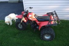
RE: the Honda trike BAAAASTARD That would have to be a collectors item now wouldnt it!! i had the same model back in 84-85ish they are a
BLAST to ride pitty they stopped making them, heap more fun than a quad. And look Doc its right way round too
a fully equiped workshop, best of luck with the rest of the build anywayz looks awesome thus far bet your hangin to take it for a blat too...
RE: the Honda trike BAAAASTARD That would have to be a collectors item now wouldnt it!! i had the same model back in 84-85ish they are a
BLAST to ride pitty they stopped making them, heap more fun than a quad. And look Doc its right way round too
Ypedal
100 TW

Ypedal
100 TW
AussieJester
1 TW
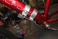
Those two stage drives sure do fold up smaller than i thought, brings their
size into perspective when you see them mounted on the bike, nice job too BTW.
I can't see any rust though bud where tiz it? on the drive sprocket
is it? I know mine rusted, what i did was spray a light film of WD40 over them
evey few weeks haven't had a prob since, obviously collects a lil dust though lol..
NOW...FINISH IT and get us some video of you rippin !!!!1111oneioneone lol
KiM
Ypedal
100 TW
Yeah. the bigger 2nd stage sproket rusted out early on, i plan to buff it out good and wax coat it once i get the rest of the chores done.. right now i just want to get this up and running for a test ride.. but before i get to do that i have to ream out the chain slot a bit wider, and make 2 chain tensioners (1 for the fw to chainrnig, and 1 for the main chain ) then wire it all up.... will likely start off on 24v and ramp it up if everything holds together.. :lol:
mwkeefer
1 MW
Ypedal,
The build is coming along nicely, I really appreciate the careful masking off of the frame you did before searching for suitable mounting locations... shows a true professional touch (this is the same thing any and all good mechanics do before repair/diagnosis work, rebuilders, craftsmen of all kinds).
When you said that most installs were an Angle Grinder... I thought maybe you were slightly kidding, I see now your not ! That is an awful lot of work to do by hand and with an angle / bench grinder? WOW.
I must admit I have nearly 8 grinders in total, 4 cutting tools a variety of sanders and my ever useful Dremels but I frequently pack up the project when things get this hairy and head down to a local machine shop (that owes me a few favors).
I may have missed it but are you planning an enclosure, chainguard or fairings to cover the motor and chain or are you gonna let it all hang out = )
-Mike
PS: Be careful you don't chain grind yourself, the drives are a work of beauty but... seriously scarry in motion (especially 1-2" from your inner thigh).
AussieJester
1 TW
mwkeefer said:I may have missed it but are you planning an enclosure, chainguard or fairings to cover the motor and chain or are you gonna let it all hang out = )
.
Personally i hope not i LOVE the "naked" look seeing Matts drive is mechanical Pr0n although a chain guard would be sensible and
a good idea it would be a shame too cover things up IMHO....You could possibly use a plexi or lexan in clear for chain guard i guess?
KiM
recumpence
1 GW
In his location, a guard is not needed for normal riding. However, if the bike is crashed and lands on his leg with the drive running, his pant leg could get caught.
Matt
Matt
mwkeefer
1 MW
Matt,
Ive seen vids of your drive units in Ys type of bike (not specific mount point) and it's only the crash or a broken chain that would concern me. I didn't mean to insinuate that your drives aren't safe... just that its best to be careful and more of a joke for Y and general caution for others...
Sry if it didn't come across that way.
-Mike
PS: Lexan or other clear "display" cover would be sweet and protective = )
Ypedal
100 TW
Already on it.. i have 1/4" lexan on hand !! :wink:
recumpence
1 GW
Cool!
You know you can heat up Lexan (Polycarbonate) and bend it into cool shapes. 8)
Matt
You know you can heat up Lexan (Polycarbonate) and bend it into cool shapes. 8)
Matt
Ypedal
100 TW
Yep ! I have heat guns and even a pupose built heat strip on hand !! ( have not used it yet but i got it for my chopper project along with a few 4x8 ft lexan 1/8" sheets !! woot !
I have some experience working witih lexan from my Norco.. fun stuff !
I have some experience working witih lexan from my Norco.. fun stuff !
Ypedal
100 TW
Small update, got the 2nd chain mounted and went for a pedal test, so far so good ! .. Started work on chain tensioners that are going to be required, even with half link chains you can't get them tight enough to work eithout tensioners.. grrrr.. i have most of the parts i need in my parts stash, bearinged rollers and various springs, hopefully get that sorted out tomorrow night.
Popped a few wheelies and intentionally landed hard to test the bracket, so far so good, everything is still in line and solid.. for now... :lol:
.. Started work on chain tensioners that are going to be required, even with half link chains you can't get them tight enough to work eithout tensioners.. grrrr.. i have most of the parts i need in my parts stash, bearinged rollers and various springs, hopefully get that sorted out tomorrow night.Popped a few wheelies and intentionally landed hard to test the bracket, so far so good, everything is still in line and solid.. for now... :lol:
AussieJester
1 TW
Videooooooooooooooooo please Yman
KiM
p.s do you also have a single stage drive there by chance? need the length of them in open and closed position and im looking to finalise the end part of my frame today, i haven't been able to find the page its on in the reduction drive thread :-S
KiM
KiM
p.s do you also have a single stage drive there by chance? need the length of them in open and closed position and im looking to finalise the end part of my frame today, i haven't been able to find the page its on in the reduction drive thread :-S
KiM
MitchJi
10 MW
Hi,

One foundational aspect of my drive system is a 1 and 1/8 inch OD bearing.
Here is a quick sketch of the drive unit. You can see how it can be laid out or folded up, or any position in between.
The shaft centers are 3 and 1/2 inches apart for the secondary drive and the motor is mounted on a slotted plate for belt tension adjustment.
There will be various mounting tabs for it that are not shown. But, this gives you an idea of the actual drive. This was drawn on 1/4 inch square graph paper at roughly 1/2 scale.
I just realized my reduction drive drawings are off a bit. The motor plate shows (in the sketch) to be 7 inches long. That is not correct. The motor plate will only be 5.5 inches long.
The large belt pulley is 4 inches diameter and the #25 secondary sprocket is nearly 5 inches in diameter. This drive will be setup as 16 to 1 to begin with. I can go down in motor pulley and small secondary a few teeth each for a 24 to 1 ratio. Any lower and these parts will be larger.
Bear in mind, the photograph (SKETCH) shows very large pulley and sprocket. These are the absolute maximum size for a very drastic reduction ratio. Most drives would use much smaller pulleys and sprockets.
Similar threads
- Replies
- 49
- Views
- 3,290
- Replies
- 16
- Views
- 1,031
- Replies
- 22
- Views
- 14,438
- Replies
- 12
- Views
- 4,399