Yuntong 48V 20 ah BMS Failure??

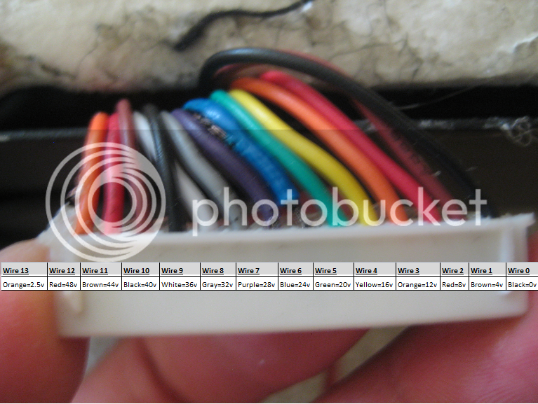
I couldn't take the battery out but I did as above poster stated. I melted the glue, took out the white connector and measured voltages individually this way. All of them increased in 4 volt increments except for the black wire, which I assume was ground as no reading present, and also one of the two orange wires as it was a reading of 2.5v (which looks like the cell number 13??). See picture below. Important Note: for whatever reason, each time I take a voltage reading of that orange wire, the voltage decreases. It is now down to 1.8v (originally 2.5v).

whiteconnector.png
 
You can actually measure each individual cells voltages, move the negative probe along with you to the next cell instead of keeping it on the black wire.
 
the red wire we talked about before and the orange wire both come from the top of #13. since there are 14 wires i am sure you have 13 cells.

so the orange wire where it goes into the plug there and the red wire to the processor should be soldered to the same spot on top of #13. so you can check for continuity of the connection from the pin on the plug for the orange wire over to the red wire. that would confirm the wires are connected, but it does seem like they may not have good contact with the cell. so maybe the tab of the cell has broken off underneath the pcb where you see them soldered down.

if the tab made intermittent contact it would give voltage sometimes and not other times. otherwise the voltage would remain steady if the cell is connected.

also the base of the wires where it goes into the plug for the blue and purple wires looks like they have melted. whats up with that?
 
999zip999 said:
Post cell voltage like

1. 4.00v
2. 3.99v
3 3.85v


13. 4.00v

999zip999, I'm not sure how to do it this way, I only know how to get cumulative readings. I do this by placing black probe on B- and red probe on each wire connection in the back of the big white connector. I know you said to "move along" but I don't know what you mean by this. Can you advise me on how to get my voltmeter to display individual reads rather than cumulative?

dnmun said:
the red wire we talked about before and the orange wire both come from the top of #13. since there are 14 wires i am sure you have 13 cells.

so the orange wire where it goes into the plug there and the red wire to the processor should be soldered to the same spot on top of #13. so you can check for continuity of the connection from the pin on the plug for the orange wire over to the red wire. that would confirm the wires are connected, but it does seem like they may not have good contact with the cell. so maybe the tab of the cell has broken off underneath the pcb where you see them soldered down.

if the tab made intermittent contact it would give voltage sometimes and not other times. otherwise the voltage would remain steady if the cell is connected.

also the base of the wires where it goes into the plug for the blue and purple wires looks like they have melted. whats up with that?

dnmun, I never thought of those wires being melted, they looked more frayed or stressed but now that I think about it they shouldn't be. The only thing I can think of is that I shorted something earlier when I first started measuring the voltage. I believe one of my probes touched in two places at once because I saw a little bit of smoke. :shock: I remember this happening when the probe touched somewhere near the area shown in the picture below. Hopefully I didn't ruin it.

As far as the orange wire, I always was able to get a reading, it was simply perplexing that each time I did take a voltage reading, each subsequent reading was always lower than the prior one! Also, you stated to "check for continuity of the connection from the pin on the plug for the orange wire over to the red wire". Not sure if I understand this piece as far as testing it.
 
those two wires may have pulled out of the plug housing when you pulled the plug out of the socket so more of the end is exposed.

about the continuity test of the orange wire to the red wire that carries voltage to the processor: since we caan't see the place where the red wire and the orange wire are soldered to the tabs on top of the little pcb connection board, i felt you could establish if they were still making connection by checking continuity between them since they are soldered to the same place.

the 2.5V dropping in value implied there is not a good connection to the cell, so i wondered if the orange wire was no longer soldered onto the top of cell #13 so all we could go by is checking continuity of the two wires to each other since they are soldered to the same spot.

but that is where the problem is. either #13 is disconnected or not charging up for some reason. if your charger puts out the 13x4.2V=54.6V then it may not have enuff charger voltage to fill it up to begin with and you just have an undercharged cell. but the voltage should be stable.
 
dnmun, I understand the logic behind doing a continuity test. However, I've never done one before. I looked some info online and found out that for continuity test I need to switch multimeter to "ohms" setting. Then I place each of the two multimeter test probes on the orange and red processor wires. If the amount of resistance shows zero, then the wire/circuit is open or broken. Can you confirm? Am I correct in my understanding? If so, I will test this way tonight.
 
yes, you are checking to see if the connection between the two wire is continuous. if you can see where they attach to the battery tabs that would be ok too.

you can only check continuity if the entire wire is at the same potential or that voltage will force current through your meter and perhaps damage it but if the wire is open the reading of the resistance is open circuit.

from what you said earlier about the cells being glued in place, i suspect they have just swollen up so much they are jammed inside the case now.

i have seen the tabs break off underneath the pcb on other packs and i am thinking that could account for the sudden failure but it could be because your charger does not put out enuff voltage to make all the cells charge up to the 4.2V level for the lipo or li ion whichever you have. but i think the BMS itself is ok.

if it turns out that the #13 is dead then we can figure what to do then but why the voltage drifts around, or down as you said, is where the clues are now imo.

if you can measure while pushing the pcb down from the top, wiggling it a little to see if the tab is broken underneath without having to pull the pouches out will help. by pushing down the tab would make contact intermittently and then when pulled apart it would go open circuit. so that would be the best path to follow now, along with measuring the actual voltage output of the charger to prove it gets up to 55V.
 
coloradoebiker said:
dnmun, Then I place each of the two multimeter test probes on the orange and red processor wires. If the amount of resistance shows zero, then the wire/circuit is open or broken. Can you confirm? Am I correct in my understanding? If so, I will test this way tonight.

nitpicky, but if the ohm meter shows "Zero" or very close to it ~.2 ohms, then you have a short.


if the ohm meter shows Very high, like over 70K ohms or very close to it , then you have an open circuit.

d
 
I can see that you shorted wire 6&7 together with your meter probe. I'm glad it's this though, as at first I thought something conductive had been rattling around in there doing all sorts of damage.

Have a look at this. It is a diagram of how a bms watch's the cells individually. http://endless-sphere.com/forums/viewtopic.php?f=14&t=20971&hilit=oz890#p305530
If you want to look at the voltage of cell 13, you measure between your orange(wire13) and red (wire12)

Still looking at that pic, you can see that the orange comes off the end cell for the bms to monitor it, and also another wire comes off the end cell to actually use it. Dnmun is asking you to check both wires are still attached. Not by physical means, but by electrical testing.

I'm interested in cell 13, So I would test cell 13 with my voltmeter on the orange and it's neighboring red.
 
dnmun said:
you can only check continuity if the entire wire is at the same potential or that voltage will force current through your meter and perhaps damage it but if the wire is open the reading of the resistance is open circuit.

Per your above statement, you're saying that if I run this test I might fry my multimeter? How could I test it then?.......
 
I put shrink tube up to the end of the tip of the MM probe so not to have much of the probe end exposed. For the pre cell voltage you move both probes down one notch. Move the black probe down one notch and the red probe down one notch for single cell voltage. That wqay you get the voltage reading of each cell. Probe brn and red, red and orange, orange and yellow, yellow and blue . ect.
 
999zip999 said:
I put shrink tube up to the end of the tip of the MM probe so not to have much of the probe end exposed. For the pre cell voltage you move both probes down one notch. Move the black probe down one notch and the red probe down one notch for single cell voltage. That wqay you get the voltage reading of each cell. Probe brn and red, red and orange, orange and yellow, yellow and blue . ect.

Ohhhh. Ok. Both of what you and friendly1uk said about how to measure single cell voltage now makes sense. :lol: I did not know this. Just learning all this electrical stuff from scratch so thanks. To clarify, as far as the shrink tube, are you making this recommendation out of precaution so as not to accidentally short something again like I did with wires 6 & 7 or is this in precautuion to prevent multi-meter from frying from continuity test as Dmun states above?
 
By putting the shrik tube on the probe only the small part of the tip is showing. Can use black tape also. Also check as Dmumn said that the wires havn't backed out of the white plastic bms plug as they sometimes do.
 
999zip999 said:
By putting the shrik tube on the probe only the small part of the tip is showing. Can use black tape also. Also check as Dmumn said that the wires havn't backed out of the white plastic bms plug as they sometimes do.

I don't think they did but I will double check and will probably need to solder if this is the case. You didn't answer my clarification question....
 
cell # 13 has singular cell voltage reading of -44.4 volts. All others appear to be 4v. Not sure if this battery is worth deconstructing and rebuilding for the one cell, especially since the previous owner has used it to commute to work 11 miles during the summer so I would guess 100-200 charge cycles. This means even if the one cell is replaced, the other cells are likely to go bad at anytime, not to mention they may have been affected by heat discharge from the first one going bad. Also, seeing that the voltages are are 4v, people tell me this means that this battery is likely not lifepo4.

Let me know what your guys' thoughts are? Also, does anyone know which shipping companies are willing to ship LIFEPO4 batteries? If I buy a used battery from someone, most companies won't ship it as its "hazardous"?
 
Back
Top