"Zephyr" - Finally, the "v4" Fechter/Goodrum/Hecker BMS...

I was a bit hasty in my previous post and am nursing one hell of a headache. Have just waded through a few pages and am interested, but would like to know how this BMS differs as in it's a shunt based ...differs from the normal bleeding BMS?
 
Sorry for the delays. :)

I agree, we need a better way to get to the latest info. I will either edit the first post, or we'll start a new thread for the new version.

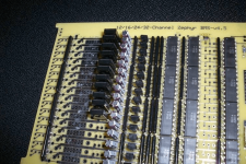
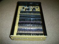
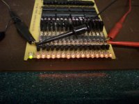
What is different about this new version, which we will call v4.5, is that it has a new/simpler control scheme for determining end-of-charge, and that we are now using resistor arrays and quad opto chips which cuts the assembly/build time down significantly. It used to take me several hours to bend the leads, install, solder and trim the leads for the hundreds of resistors on a typical 24-channel board. Now, using the resistor arrays, that time is cut down to about 20 minutes. :) Here's what a partially assembled board looks like:
16s Zephyr BMS-01.jpg

16s Zephyr BMS-02.png

There are two main differences between this Zephyr BMS design and the typical Ping/Signalab-type boards. The latter typically only have bypass currents of 50-75mA, which means it literally can take over 24 hours to balance a reasonably imbalanced pack. The Zephyr shunt circuits can pass about 600mA, or about 10 times as much bypass current. Even the new Zephyr "Lite" BMS variants, which we are also working on, primarily for embedded LiPo setups, can pass about 160mA of shunt current.

The second major difference between the Signalab, et al, and Zephyr designs is the way charge control is handled. In the typical designs, the HVC trip point is set pretty high, like around 3.70-3.80V for LiFePO4. As soon as a cell voltage hits this point, the charge current is cutoff and the shunt circuits then bleed current off until the high cells are back down until the cell voltage is below the turnon point for the shunt circuit, typically around 3.60-3.65V. At only 56-75mA, this can take hours. This is not the most efficient way to do this, but it will eventually work, as long as all the cell voltages are above the shunt turnon point once the charge current is cutoff. For healthy cells, that start out reasonably balanced, this works okay, but like I said, can take awhile. If, however, you have a weaker cell, with slightly less capacity, or some that for whatever reason are significantly out-of-balance in relation to the rest, you can end up where cells get full faster. When that happens, the voltages for those fuller cells will rise sooner than the rest, and will trip the HVC line too soon. Now you have a case where the bulk of the cells haven't reached the shunt bypass turnon point, so only the fuller cell shunt circuits will come on. This will bring the high cells down closer to the rest, but it does nothing to balance the rest of the cells. What needs to happen is that the whole charge cycle needs to be repeated until all the cell voltages will at least be above the shunt turnon point when the high cell trips the HVC line.

The new Zephyr control scheme works differently. There are actually two separate HVC lines, one set a bit higher than the first one. The higher, second HVC signal is used as a "failsafe" control, to catch those cases like the one described above, where a weak, or severely imbalanced cell gets full way before the rest of the cells. We don't want this errant cell to get into an unchecked voltage rise condition, so whenever this line gets tripped, the charge current will be turned off briefly, for about 1 second. During the off cycle, the shunt circuit will pull the cell voltage back down closer to the rest, and then the charge current is turned back on. This cycling will repeat until the rest of the cell voltages catch up to the point that the shunt circuits themselves can keep the high cells in check. With 500-600mA of shunt current, it takes a pretty out-of-whack cell to trip this "failsafe" HVC signal. Under normal conditions, with normal imbalances, this HVC cycling condition shouldn't occur. When it does, it is a good indication that something is amiss.

The other HVC signal is tripped for each cell circuit when its shunt is in full opration, which means this cell is full. The opto outputs for these HVC signals are connected in series, instead of in parallel, like with the "failsafe" HVC and the LVC lines, and then this series connected opto string is used to trip the end-of-charge cutoff logic. This is a much simpler, and more reliable way to do the cutoff logic. In the previous versions, we were measuring the charge current and waiting for it to drop down below some user-adjustable setting, and then cutting off the charge current. This scheme works, but each setup is different and we've seen numerous issues in various setups. The new scheme is pretty much "one-size-fits-all" and it doesn't require any user adjustments.

The Zephyr Lite variants are functionally equivalent, but with shunt currents low enough that the boards can be safely embedded with the LiPo packs. It has been my experience that LiPo-based setups stay much more closely balanced, under normal conditions, so less shunt current is fine. The charge control section is identical to what's on the full Zephyr board, but as shown in the example shown below, it is sized to fit in the smallest Hammond 1" x 2" x 3" extruded aluminum case:
4x6s Embedded BMS Lite-v4.4.10a.png


I'm not too sure on the pricing, for either the full Zephyr unit, or for the Lite variants, but the overall costs should be less than the previous versions. The board sizes are smaller and the total parts count is down quite a bit. For the full Zephyr boards, we will at a minimum offer the PCBs with a detailed set of instructions and a BOM file. We may, however, also offer pre-built and tested versions, once we get these going. I don't know how much extra this will be until we get an idea on how long it now takes to build one. Richard is working on this now. For at least the LiPo Lite version shown above, we will definitely offer these pre-built/tested, at an attractive price. More about this later (please don't send me a PM requesting prices and availability yet. :lol: ).

We will also be starting "For Sale" threads in the for sale forum section, for each of these, and like I said, I will either update the first post in this thread, or we'll start a new "info" thread, with all the appropriate data in the first post.

-- Gary
 
It's not quite 'fully baked' yet, but it's close. I don't want to declare success until it passes all the validation testing. 4.5 takes uses the throttling and auto power scheme from 4.4 and throws in a modified version of the successful ver 2.x end-of-charge detection. This eliminates the need for adjustments on the board and maintains the reduced heat output feature of 4.4. It should be fairly tolerant of charger voltage variations and play nice with most chargers. LVC relay option allows for highly flexible LVC connections that will work with virtually all controllers and there is a provision for audible/visual alarm connections for those that don't want a throttle interrupt. The real breakthrough is the use of resistor arrays to cut down on the assembly time. Great idea Patrick :wink: It works fantastically with through-hole parts.

4.4 is still the big daddy in terms of shunt current. 4.5 is designed at 500mA but generally runs a bit higher. For very large cells or large imbalances, 4.4 will have a speed advantage.
 
Sounds good, with the Lipo version would we be able to have the option to ...well...here is my Lipo charging setup:

I have 6 x 8S 5.8Ah Turnigy Lipo wired up for 16S 3P with the balance leads all wired up in parallel for simple balancing. I charge using a Kingpan standard 12A but adjusted to 63.4V so that my cells are kept at around 4.12 to 4.15v when bulk charging.

Can your Lipo Lite BMS be setup to not let cells go over say 4.14v to keep the cycles higher as a lot of people do not like having cells charged to 4.2v?


Doh! Further reading of the other thread says that you like to charge to 4.16v I think which is fine :)
 
Build still in progress:

Most other commercial circuits allow the high cells to go to a much higher voltage at end of charge and the charge terminates as soon as the first cell reaches this level. With the new versions, all the cells must reach the set point to terminate charge, so balance is forced on every cycle, yet none of the cells are allowed over the set point.

Another feature, also found on the 4.4, is my patented HVC delay function, which allows for throttling the charge current by switching the charge current on and off at a very low frequency (around 1Hz), yet maintains the fastest possible balancing for a given shunt current. This eliminates the screeching/blown charger problems some encountered with the high frequency ver 2.x board throttling system. If the cells are well matched, the throttling function will never kick in, but if there is a significant imbalance, it will correct the balance in the shortest possible time, then terminate the charge.

Another 4.4 feature carried over is the automatic power switch. Previous versions required either a manual start or a third wire and jumper on the charger connection to switch on the control circuit when the charger is connected. Now, anytime the charger voltage is greater than the pack voltage, the control circuit automatically comes on.
 
Spacey said:
Sounds good, with the Lipo version would we be able to have the option to ...well...here is my Lipo charging setup:

I have 6 x 8S 5.8Ah Turnigy Lipo wired up for 16S 3P with the balance leads all wired up in parallel for simple balancing. I charge using a Kingpan standard 12A but adjusted to 63.4V so that my cells are kept at around 4.12 to 4.15v when bulk charging.

Can your Lipo Lite BMS be setup to not let cells go over say 4.14v to keep the cycles higher as a lot of people do not like having cells charged to 4.2v?


Doh! Further reading of the other thread says that you like to charge to 4.16v I think which is fine :)

Yes, you can simply set the charge to voltage to about 4.15-4.16V per cell. It will balance all the cells to around 4.14V.

What is shown above is 4 x 6s boards, but we will also have 8s versions as well. :)

-- Gary
 
fechter said:
4.4 is still the big daddy in terms of shunt current. 4.5 is designed at 500mA but generally runs a bit higher. For very large cells or large imbalances, 4.4 will have a speed advantage.

A semi-noob questions :?:
What is considered to be a very large cell? I use LFP 12S 16 AH. Should I buy a v4.4 instead of a v4.5?

I am looking forward to the release of v4.5 and if it is not too much to hope for. A website which is not under construction :evil: . but seriously..great work and do not work yourself to death :D

/krelle52
 
krelle52 said:
A semi-noob questions :?:
What is considered to be a very large cell? I use LFP 12S 16 AH. Should I buy a v4.4 instead of a v4.5?

I am looking forward to the release of v4.5 and if it is not too much to hope for. A website which is not under construction :evil: . but seriously..great work and do not work yourself to death :D

/krelle52

By large, I'm thinking 100Ahr car-sized cells. For 16Ahr, the 4.5 shunt levels should be fine.
 
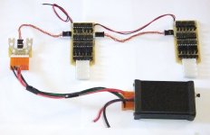
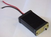
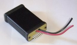
Here are some shots of the new Zephyr "Lite" embedded BMS 6s4p boards, along with the small separate Charge Controller unit:

12s LiPo Embedded BMS Lite-01.jpg
Zephyr Charge Controller-02.jpg
Zephyr Charge Controller-01.jpg
View attachment 2

These boards are not just simple LVC/HVC boards, like I've done in the past. These are full-blown BMS boards that add cell balancing, plus the same two-level HVC and LVC protection functions. As many of these 6s4p boards that are needed can can be daisy-chained together, to support multiple pack configurations. The two-wire LVC signal can be tied into the throttle signal or a controller's ebrake input. The two HVC signals are daisy-chained between board using comon RC servo cables, which are available in a large variety of lengths. There is a special adapter that the end unit servo cable plugs into that combines these signals with the main pack charge + and - connections. These also have spots for 4mm bullet plugs, so the main pack leads can be paralleled as well. I have two other versions of this adapter, with support for 4p 4mm bullets and a 2p setup for 5.5mm versions, found on some packs.

A single charge cable which has the main pack charge leads, as well as, the HVC signals, plugs into this adapter and can then be brought out to the outside of the pack. The new standalone charge controller has the mate for this plug coming out of one end of the small box. The only oher connections are then the two + and - charge connections that are connected to the charger/supply.

I'll have more info about this new "Lite" setup, including pricing and availability, in the coming days. :)

-- Gary
 
where is our steve jobs giving the release presentation?

we should have bands playing and politicians with speeches.

this is a really proud moment for you guys, it has been a pleasure to try to just understand and appreciate how far you guys have come in just a few years.

congratulations of the highest order! you guys did a great job, and put up with a lot of questions, this has to be one of the biggest things on the sphere, congrats to both of you!
 
fechter said:
4.4 is still the big daddy in terms of shunt current. 4.5 is designed at 500mA but generally runs a bit higher. For very large cells or large imbalances, 4.4 will have a speed advantage.

Is 100Ah considered a big pack, I have a 5P 24S pack of A123 Prismatic Cells 20AH, should I go with the 4.4?

Could you link the Parts list and Instructions for 4.4?
 
Looks like I will be ordering a 16Cell Lifepo4 and a 16Cell Lipo BMS off you when they are ready :)

I hate having the Lifepo4 cells held in a 3.7v state that some BMS do when balancing.
 
dnmun said:
where is our steve jobs giving the release presentation?

we should have bands playing and politicians with speeches.

this is a really proud moment for you guys, it has been a pleasure to try to just understand and appreciate how far you guys have come in just a few years.

congratulations of the highest order! you guys did a great job, and put up with a lot of questions, this has to be one of the biggest things on the sphere, congrats to both of you!

Thanks. :oops: :)
 
SlyCayer said:
fechter said:
4.4 is still the big daddy in terms of shunt current. 4.5 is designed at 500mA but generally runs a bit higher. For very large cells or large imbalances, 4.4 will have a speed advantage.

Is 100Ah considered a big pack, I have a 5P 24S pack of A123 Prismatic Cells 20AH, should I go with the 4.4?

Could you link the Parts list and Instructions for 4.4?

With higher C-rated cells, like the a123s, they won't get out-of-balance much at all, so the v4.5 variants are going to work just fine. Richards 100Ah comment I think was more directed at setups using the fairly low C-rated ThunderSky-type cells. Even there I think 600mA shunts are going to work just fine. It might take a little longer to balance (1/2 hour? An hour?), but if you are charging overnight it won't matter.

-- Gary
 
Any chance of a higher series count (like the old ones you could snap off bits to extend)?

I'm looking at it for 44S Lifepo4, 40AH cells. Obviously power supply and charge control mosfet will require revision...
 
heathyoung said:
Any chance of a higher series count (like the old ones you could snap off bits to extend)?

I'm looking at it for 44S Lifepo4, 40AH cells. Obviously power supply and charge control mosfet will require revision...

Yes, you could extend the board like previous versions. 44s might be pushing the creepage distance in a couple of places but conformal coating would take care of that I think. The main charge control FET would probably need to be changed as well, but it really only needs to handle the difference between the charger voltage and the lowest expected pack voltage.

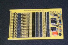
The rest of my parts finally arrived. Here's what the 16s prototype looks like:
Build pic 5.jpg

We're planning to rearrange things a little to make construction easier, so the final layout will be a bit different. Next I need to get it all wired and do some testing with the pack attached.
 
This looks really good. I'm looking forward to using this BMS in my 24S, 40Ah scooter.
 
Ever since andyh dissapeared I have been looking for a plug-and play BMS. Almost spent 600 on a lithiumate bms because I was so tired of disconnecting and reconnecting batteries. Sooo glad that it has finally arrived.
 
It's alive! :twisted:Build pic 6.jpg

Here's what I got for the set point voltages using the LiFePO4 parts:

58.2v total

3.627
3.638
3.627
3.631
3.631
3.644
3.652
3.646
3.642
3.632
3.636
3.628
3.633
3.631
3.628
3.638
3.638

We're using 2% parts, so that amount of variation is within the expected range. As far as the cells are concerned, this amount of variation represents a negligible difference in capacity. We are constrained by what resistor values are stocked by the parts places, so it's hard to get exactly on target.
 
Sorry for the bad focus, it's a cheap camera.
Test showing charge cycle:

[youtube]jKReGrHIpFA[/youtube]

Testing is going well. The circuit is working the way it is intended and there aren't any unanticipated issues. I like the way it balances and the balance cycle seems to be much quicker than previous versions. The next issue is getting the board optimized for the enclosure and to make assembly easier.
The version shown in the latest pics and video was good for validation testing, but we want to get rid of the wires attached to the board and get connectors instead. This will save lots of assembly time and generally make things easier.

Under extreme conditions the board can still get pretty hot, so I'm working on an overtemp safety. Under normal conditions with healthy cells, balancing happens so fast it doesn't have time to even get warm.
 
Here's a little cleaner shot of the board in action. After running several cycles, the cells became so balanced that the balancing time was extremely short. I had to place some drain on individual cells to create some imbalance so the board had something to do.

It's flying with the covers off in the test setup, but we'll get all those wires coming out the back end with connectors.

I set the charger voltage about 1v higher than the threshold where the shunts come on. This keeps the charger in CC mode right until it kicks off

[youtube]OZxGiTMM3T8[/youtube]
 
The videos look good. Seems like things are working like they should. :)

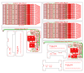
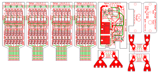
Here's where we are with the layouts:

12-16-24-Channel Zephyr BMS-v4.4.9f.png

As Richard said, we both felt having connectors was better and I really like how easy it is to make cables for MTA156 connectors, so that's what we will use. These will be the right-angled versions, and will stick out through cutouts in the custom end plates. This way, the pack connections can be made all at once, and can be done with the box all buttoned up.

In terms of configurations, we decided to split off the 12 and 24-channel versions into the slightly smaller Hammond boxes. We were a bit concerned about having 32-channels worth of heat in one box, and I wasn't really happy with simply not populating the same boards for 12 and 24-channel options. Anyway, this is a better solution, I think. We also made it easier to "daisy-chain" multiple boxes together, so lots of additional higher voltage setups can be supported (16 + 16, 24 + 12, 24 + 24, 16 + 16 + 16, 24 + 24 + 24, etc...). There will be 4-wire male/female pigtails, like the ones used on the CA, etc., that can be used to connect multiple boxes.

The only thing left to add is the new temp control, which Richard will test early this week. Basically, it will simply pull down on the HVC "ANY" line if the temps inside the box gets too toasty.

One other change that we are making both to the full Zephyr boards, and to the Lipo-based embedded Lite units, is a replacement of the "touchy" 5.1V zeners with some TVS diodes. The main purpose of the zeners is to protect the TC54 detectors from blowing, due to mis-connections or broken cell connections. One way this can happen is when cell connections comes loose, or are not plugged in at the same time. This can cause the TC54s to see too much voltage, which causes them to fail. The zeners have taken care of this problem, but I've found they seem to blow just by looking at them crossly. :roll: The other day I was testing the trip points for the HVC signals on one of the 6s embedded boards and I inadvertently bumped up the supply voltage a bit too much. It might have actually been a voltage spike from the supply. Anyway, the zeners did their job but all six of them fried. When they fail, they dead-short, which would've popped a fuse trace, but the supply was current limited to about 2A. The new TVS diodes will still protect the TC54s, but they won't fail, like the zeners. They are also not too much bigger than the zeners, so this will be a simple replacement, not a layout change.

-- Gary
 
Spacey said:
Would really help to have costs simply displayed etc and also how this BMS differs from the normal Chinese BMS etc
35 pages is a lot to wade through, I am interested in a 16 cell one but have no idea on price/build/info
+1, and make that 37 pages as of today.

Please have the webpage up asap. I assume it will have different categories for the full-fledged as well as the lite version. And please make it readable to people with basic to moderate understanding of battery management but not necessarily equipped with a EE degree.
 
Back
Top