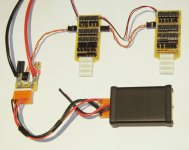
"Zephyr" - Finally, the "v4" Fechter/Goodrum/Hecker BMS...

It's getting there. The new temperature sensor works great and we will be able to easily program the temperature set point. The temp sensor will pause the balancing cycle if the box gets above the set point. If the box is located where it can dissipate the generated heat, the sensor should never activate, but if the box is burried where it doesn't get any air for example, it could get hot.

I've also made a slight change to the mode indicator LED to make it more useful. It will now show solid red during bulk charge, go orange or blink during balancing and go solid green at end of charge.

Anytime changes are made, we need to fully build the board and test to make sure there aren't any wiring errors or fit problems, so yet another delay in release.

Here's a picture of the prototype unit that gives a better idea of size. This is a 16s unit:Build pic 7.jpg
 
This may sound dumb, but do I need 2 of these for a 2P setup ?

I have 16S 2P Zippy, so would I need to connect all the red and black balance wires together and then connect to the bms ?

Do you think you could offer leads to connect up in such a setup ?

Thanks
 
On 16s unit would work for your pack. I believe Gary has the balance wire combiner boards that would combine the parallel packs. The wires from both parallel packs need to be connected together.
 
Hi guys enjoying the thread.
Like your lite for a A123, 20AH, 24S putting together, just got a question.
I'm concerned about short circuit protection from the battery pack,noticed many bms involved in battery packs with high s/c currents are generally mounted atop the battery, was hoping to look at a mod to your lite setup for the A123's that would suit the Al tabs as well, but can't find your circuit diagrams, only pcb layouts, i suppose it would, understandably,be proprietary to you, but would like to look at keeping any connections leaving the pack short and protected at the source end, don't like the idea of external wiring or a pcb track acting like fuse wire if a fault occurs.
 
Unlike most other BMS, the discharge line does not pass through the circuit. You need to use your own fuse/wiring to the controller and the controller does the current limiting. Only the charge line goes through the circuit.

The low voltage cutoff acts on the throttle or key line going to the controller to stop discharge.
 
fechter said:
Unlike most other BMS, the discharge line does not pass through the circuit.
To me, that is one of the best feature of your BMS.

When are you guys going to have a website or a sale thread for the many versions of your BMSs? I want to be able to compare different versions against one another to decide which is best for me. But wading through several long long long long threads is not my cup of tea. May I suggest that you start with a comparison matrix?
 
Thanks Fechter and Sam for the endorsement.
I'd like a setup to connect to the 24S pouches was it yourself to pm for it fechter?
 
SamTexas said:
When are you guys going to have a website or a sale thread for the many versions of your BMSs? I want to be able to compare different versions against one another to decide which is best for me. But wading through several long long long long threads is not my cup of tea. May I suggest that you start with a comparison matrix?

This whole process has been agonizingly slow but we can't sell stuff that doesn't work properly.
Gary will be reviving his web site once we have product to sell. This should contain a description of the various options.
The latest revision boards are getting made now, and once again we have to build/test to make sure there aren't any mistakes in the layout. We'll post here once things are up and running.
 
fechter said:
This whole process has been agonizingly slow but we can't sell stuff that doesn't work properly.
Gary will be reviving his web site once we have product to sell. This should contain a description of the various options.
The latest revision boards are getting made now, and once again we have to build/test to make sure there aren't any mistakes in the layout. We'll post here once things are up and running.

I have started offering the "Lite" version, which uses 6-channel or 8-channel boards that can be embedded in with the packs, and uses a separate charge controller that is mounted in a small box, but these are really geared towards LiPo setups because each of these boards also acts as a parallel adapter for the individual 5s, 6s or 8s LiPo packs that make up the completed battery. The reason these are called "Lite" is because they have lower shunt currents, which means they don't generate a lot of heat, like the full Zephyr circuits can do, which is why they are mounted in an aluminum box. Healthy LiPo cells/packs tend to stay prett well balanced, so large shunt bypass currents aren't really required. Also, since the Lite 6s and 8s boards are typically embedded in with the packs, there aren't any individual LEDs on each channel. All of this reduces the complexity of the boards and lowers the parts count, which makes them much easier and faster to put together. Here's what a typical 12s LiPo setup would look like:

6s4p Lite BMS-08.jpg


For LiFePO4 configurations, I'd really recommend the full Zephyr setup. It will be available soon, hopefully before the end of the year. The exception might be for a123-based setups, because it has been my experience that treated properly, these high-C LiFePO4 cells also tend to stay pretty well balanced.

In any case, I do like the comparison chart idea, and I will try to get this done soon. Also, I hope to get a new site up before the end of the year as well. :)

-- Gary
 
GGoodrum said:
In any case, I do like the comparison chart idea, and I will try to get this done soon. Also, I hope to get a new site up before the end of the year as well. :)
Thanks. I look forward to reading both.

The reason these are called "Lite" is because they have lower shunt currents, which means they don't generate a lot of heat, like the full Zephyr circuits can do, which is why they are mounted in an aluminum box. Healthy LiPo cells/packs tend to stay prett well balanced, so large shunt bypass currents aren't really required.
This is one of the areas I don't fully understand. So "healthy" cells tend to stay pretty well balanced, but "healthy" cells age and become "less healthy". Will the Lite version still be capable of balancing those cells? In other words, is the Lite version capable of balanced charging a drastically unbalanced pack right now? How many hours does it take to balanced charge this hypothetical 6s 5Ah pack: 3.3V, 3.5V, 3.7V, 3.9V, 4.0V and 4.0V with a 5A power supply? 3 hours or less? More than 5 hours?
 
SamTexas said:
This is one of the areas I don't fully understand. So "healthy" cells tend to stay pretty well balanced, but "healthy" cells age and become "less healthy". Will the Lite version still be capable of balancing those cells? In other words, is the Lite version capable of balanced charging a drastically unbalanced pack right now? How many hours does it take to balanced charge this hypothetical 6s 5Ah pack: 3.3V, 3.5V, 3.7V, 3.9V, 4.0V and 4.0V with a 5A power supply?

Yes, both the Lite, and the full Zephyr circuits will automatically balance even a grossly imbalanced pack. The difference between the two is simply the amount of time it takes. The full Zephyr circuits have shunts that will bypass about 600mA of current, while the Lite boards will bypass about 120mA of shunt current. So, it theoretically would take the full Zephyr board 1/5th the amount of time, to do a complete balance. In reality, it is probably more like a 4:1 difference. By comparison, most of the imported BMS boards cn only manage 50-60mA.

Anyway, when I say healthy cells, I mean ones that haven't lost a lot of their capacity yet. With LiPos, even as they age, the capacity numbers might start dropping off a bit, but generally, I've found this to be pretty uniform across a pack. One thing that will get even a healthy pack out-of-whack is when you discharge a pack down close to LV cutoff. The protection will save a cell from killing itself, but as the voltage gets close to the proverbial "cliff", the resting voltage will start dropping at a much quicker rate. this is where even very slight differences in capacities will show up. Anyway, when this happens, you can have some pretty significant imbalances. On the other hand, if you only discharge down to about the 15-20% level, the LiPo cells will stay pretty close.

I've had quite a bit of experience with a123 M1 LiFePO4 cells, which tend to act very much like LiPos, if you don't discharge them to LVC. Actuall, I had lots of times where a cell went ahead, and jumped off the cliff, ending up basically with a voltage under 1V. When this happened, I could recover them, by doing a very slow charge, but generally these "stressed" cells ended up losing about 10% of their capacity. From that point forward, a pack with stressed cells would still perform about the same, but it would need balancing with every charge, for sure.

As for your example, I can only make an educated guess. It looks like, with those voltages, overall the pack is about half empty. At 5A, it would probably take 1/2 hour, to 45 minutes to get to the point the shunts for the high cells start turning on. With imbalances that large, however, he shunts alone will probably not be able to hold the voltage for the high cells at 4.15V, so the upper HVC signal will start tripping, causing a cycling of the charge current. Because the full Zephyr shunts can pass more current, I'd guess this HVC cycling won't last all that long before the low cells have caught up enough that the shunt circuits alone can keep the high cells in check. Eventually, though, the Lite shunt circuits will get there as well, but how much longer, I don't know. Offhand, I'd guess maybe an hour?

In any case, both will get there eventually. :) BTW, all RC balancing chargers that I'm aware of, would not charge a pack with imbalances over 200mV, or .2V. Your example is four times that. :) Personally, if I had a pack that badly imbalanced, and it wasn't as a result of discharging to LVC, I'd keep a close eye on it, or take it out of commission.

-- Gary
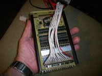
 
GGoodrum said:
I have started offering the "Lite" version, which uses 6-channel or 8-channel boards that can be embedded in with the packs, and uses a separate charge controller that is mounted in a small box, but these are really geared towards LiPo setups because each of these boards also acts as a parallel adapter for the individual 5s, 6s or 8s LiPo packs that make up the completed battery.

For LiFePO4 configurations, I'd really recommend the full Zephyr setup. It will be available soon, hopefully before the end of the year. The exception might be for a123-based setups, because it has been my experience that treated properly, these high-C LiFePO4 cells also tend to stay pretty well balanced.
-- Gary
I'm thinking of charging pouches at up to 2.5C, i expect the 50A charge current may increase required shunting for my pack if its out of wack? If this is correct i expect waiting for new zephyr would be advised as suggested.
Though if not the case with the pouches and then i still get the lite, i assume i can simply remove the parallel adapters?
fechter said:
This whole process has been agonizingly slow but we can't sell stuff that doesn't work properly.
Gary will be reviving his web site once we have product to sell. This should contain a description of the various options.
The latest revision boards are getting made now, and once again we have to build/test to make sure there aren't any mistakes in the layout. We'll post here once things are up and running.
It's commendable that you guys are so commited to wanting to produce such perfect art and I appreciate your time out spent answering my seminewb questions.
I would gladly purchase a lite as part experimental on my pack. I am considering logging each cell anyhow, so no worries.(Aussie coming thru :D ).If it's not suitable, then i will just use it elsewhere as i am building other packs.
 
I want to get one of these BMSs for my pack of 24 100AH Hipower LIFEPO4 cells, but the TPpacs web site is down. Is there another way to order it?
 
I started a "for sale" thread for the BMS Lite kit combos here: http://endless-sphere.com/forums/viewtopic.php?f=31&t=34495#p501227

Everything is in stock, and the kits will go out the same day they are ordered, from this point forward. :)

The full-size Zephyr boards/kits will be available in another couple weeks. Still some testing to do, which is unfortunately a time-consuming, but necessary process. :)

Anyway, the LiPo-centric "Lite" combos are ready-to-go. :)

-- Gary
 
Hi Gary, thanks for your time and efforts on this front, have there been any developments in the full-boards situation over the past few weeks? Many thanks. Happy New Year.

EDIT: How much do the boards figure to be sold for, and how much for the full BoM. Also, can you please recommend a particular brand of solder and soldering iron? Thanks again.
 
Gary, fechter, others,
I compliment you guys on doing an amazing job of designing and testing and even selling a BMS that should be rock solid as it does not suffer from SW bugs and other issues associated with a control processor.
There are a few issues that I do not see addressed and that is why I want to bring them up, so at least people are aware of them and possibly some might even lead to improvements of the BMS. These issues are not important as long as things go well, it is looking at the brand spanking new BMS that you have finally working well and shipping and asking myself: what if...
I will post under 3 separate headers, as I see these 3 separate issues:
- Fuses
- cell undervoltage
- cell overvoltage

The most important and immediate issue is regarding the use of fuses in the electric drive system.
All the drawings that I see, have the packs connect directly to the BMS Charge Controller without even a suggestion about protection.
For safety safe - especially when working with high voltage, high power battery packs, I suggest to have each circuit that includes a battery to also contain a proper fuse. With proper I mean DC rated, at least the voltage that the pack or charger can deliver and rated to break the peak short circuit current without exploding or creating a welding arc.
In theory the fuse can be placed anywhere in the circuit; in practice every commercial system has a fuse as the first thing from one of the battery terminals - personally I like it when you have series connected battery packs as in your drawings, to have a fuse between each contact where a red (pos) wire plugs into a black (negative) wire, because this even protects for cases where battery packs get damaged and short to the box or frame.
You might even use both fuse(s) and a breaker, the fuses to protect as last resort while the breaker is rated to disconnect as soon as the max output is delivered for longer than the controller or motor can sustain - this will protect the system from overload, even if it is lower than the max (fused) capacity. If the breaker pops during a long overload (like, driving up a hill at max throttle) then it can be reset and you can continue your trip.
 
The elegance of the Zephyr BMS is a very simple circuit for each cell, while still protecting each individual cell for over- and under-voltage; allowing full protection of each cell by shutting off charging as well as discharging (throttle) before any cell reaches its danger zone - at least in theory.
There are some limitations however:
1 - If the BMS electronics or wiring fails, then this may not be detected, so the affected cell(s) are not longer protected
2 - if a cell suddenly goes to zero volts instead of gradually dropping below 3 (or 2) volts, then there is no protection and this also leads to other problems.
3 - if a pack is not charged soon after hitting the low voltage threshold, then the TC54N continues to indicate LVC, running the cells down quickly.

The problem with wiring can happen with the inter-connection between the 6s/8s/12s boards that sends the combined LVC and HVC signals from one board to the next, if a wire breaks then all the cells connected to the boards before that point will lose protection, (whether over-charge or) over-discharge will no longer be communicated for those cells. If a wire breaks between LVC output of the last board and the throttle (or brake input on the controller) then this means that the user is no longer notified of a cell reaching the lower limit by cutting drive power. If the BMS is visible to the user, then LEDs on the board may signal to the user that something is amiss, but it is not likely that a user will see a warning LED on the BMS while riding. One possibility is to connect a warning LED closer to the field of visibility, such as on the handlebars (most eBikes already have a set of indicator LEDs there) but the problem is still that even the wires connecting these LEDs can break. Also, even if the LED lights up, that does not protect the cells unless the user decides to reduce throttle.
It is possible to make a fail-safe system, but the complexity will increase much and it is not easy to test each circuit, most likely a microprocessor will need to be added to cycle through all channels and verify that the LVC signal is enabled on each channel detecting low voltage (for example by adding a resistor between the cell and the input of the TC54N plus a resistor and transistor to ground, to simulate a low cell voltage). The throttle (or brake) signal should be clamped to ground until all circuits are verified to work. Commercial BMS'es might implement this level of self-test, but it seems over the top for a DIY system.
One thing that may be done simple and easy is to add a connector to the open LVC input on the last board in the string, so that occasionally a plug can be inserted to short the signal there, then verify that the controller cannot engage due to the trottle (or brake) signal being clamped, verifying that all intermediate LVC wiring is OK.
Another even more sneaky type of wiring failure is when one of the wires between pack and BMS fails. If one of the "end" wires fails then we lose the corresponding channel, so that cell is no longer protected. If one of the intermediate cell connections fails, then the average voltage of the two cells may be OK while the actual cell voltage is too low (or too high) and the two channels might also fail to properly indicate even when the average voltage reaches LVC, because due to the votlage dividers on the 431 references, the voltages will divide perfectly between the two channels until one channel hits LVC which will then push the other channel to the HVC condition (4.2V) while the firs channel voltage suddenly drops from 3V to 1.8V. This may be too low to reliably indicate LVC, so the two cells that share a broken wire to the BMS will then be unprotected.
Then there are cases where the electronics fails, either because a component fails or something affects the BMS board (moisture, chip of metal, loose wire) and causes the fuse to blow. This will go undetected as this channel will simply stop working, so that cell is no longer protected. Also a bad solder joint or component that fails open due to thermal, mechanical or electrical shock will render the BMS inoperable without warning.

The situation that a cell suddenly goes dead will lead to two problems: since each channel of the BMS is powered by the cell that is being protected, this means that protection fails when a cell fails. The other problem is that the total voltage of the pack drops, which can lead to problems while charging, either over-heating the BMS shunt resistors or the Charge Control FET. In extreme cases the dropped pack voltage may cause the Charge Control FET to exceed its voltage rating, since it is designed to only carry the difference between charger voltage and pack voltage, but this is not likely with a 100V FET rating. It is more likely that the increased voltage difference will cause overheating once the first channel requests throttling back the charger. The danger here is that a failure will typically lead to a short circuit in the FET (typical failure mode of most semiconductors). This means a loss of control over the charger and with one (shorted) cell less in the pack, the remaining cells will get more and will be severely over-charged...

When the pack is run down to the point where the BMS disables the discharge by enabling the LVC, the low cell will continuously see the drain of the opto-coupler LED to enable LVC. Even though the 1k Ohm resistor will limit that drain to less than 2mA, the cell will see a drain that will discharge it down to about 1.2V (the opto's LED threshold) in a matter of days. So if you forget to put the pack on charge for only a few days after running it down as far as the BMS will allow you to go, you might permanently have lost the pack. It could be wise to add a disconnect when the drain should stop, or at least add a diode in line with the LVC opto to stop draining the cell at about 2V so it has a better chance of survival, even though this change will actually cause a reduction of the reliability of the LVC, because if an already well drained pack suddenly needs to dish out a large current and the cell sags instantly from 3+ to below 2V, there will be no LVC signal because the voltage is already too low....

There probably are a couple more failure modes for low cell voltage that I overlooked, but these are what popped in my head when going through the schematic of the channel and system. In case of questions/corrections: fire away!
 
Just like the undervoltage case, the over-voltage can happen with the same type of causes:
1 - electronics or wiring problem
2 - cell failure: open circuit
3 - charger failure

If the over-voltage (HVC) signals are not reaching the charger controller, then cell(s) will be over-charged without the user knowing, this may lead to fire or at least to quick deterioration of cell performance. In particular if the "Any" HVC signal is not throttling the charger back, then some cell(s) will over-charge.
Also if a wire between pack and BMS fails, it will not detect an overvoltage until the average voltage on the two adjacent cells reaches max and if it happens to be one of the "end" wires then the channel will be dead and no protection will be present.
If electronics fails, then the HVC signal may no longer be generated or, if the failure is at the charger controller, the arriving HVC signal may not lead to throttling back.

Open cell failure is a nasty type of fault, during load the cell will try to go negative (reverse) and this might completely blow the associated channel electronics, for example the TC54N. During charging the HVC signal should throttle the charger back so the result will be that the pack will not charge at all.
During regenerative braking, the throttling is often not present, so the voltage will increase uncontrolled until the zener protection diode will shunt all current. If this situation lasts for more than a very brief moment, the zener will overheat and fail shorted, which will blow the fuse. After this there will be no more indication that this BMS channel failed unless the fuse (and electronics) are checked when replacing the failing cell or pack.

The situation of a charge controller failure is already discussed above, there is still the case where the charger starts delivering higher than usual voltage due to a failure in the charger or connection to a wrong charger. It is possible to warn for such failures (as well as for excessive low pack voltage that may indicate loss of a cell) by measuring the voltage drop across the charge throttling FET. Too high voltage drop will overheat this FET and may result in loss of control, causing over-charging of the pack at may charge current indefinitely...
 
On regen, unless you have completly full cells or really high resistance cells, the chances of exceeding the the voltage is very unlikely - especially if you have configured your controller correctly.
 
For good measure, I should say that even after writing the previous 3 posts about issues that can develop with this BMS, I am still planning to build one of these for my eBike, because I like the elegance of a minimalistic BMS and I will likely, happily, run it on one or more of my packs. I am just saying that you won't find this BMS on a commercial EV because there will be a much higher requirement for fault detection.
Still - Richard, Gary and others: cheers and thank you!
 
heathyoung said:
On regen, unless you have completly full cells or really high resistance cells, the chances of exceeding the the voltage is very unlikely - especially if you have configured your controller correctly.
It is an issue that I hear regularly from EV'ers that live on a hill - either they must take care to never charge their pack to full, or they will need some way to reduce/defeat regen when they drive/ride away from home, down the hill.
I have owned and driven an EV with AC motor and controller for about 3 years. It was capable of sending 200+ Amps back into the pack, which meant that on the lead-acid batteries that I had, the regen had to be disabled until SoC dropped to about 85% or the regen would easily push the pack voltage above the emergency cutoff voltage, which would mean a shutdown of the controller until power-cycled. Not a fun way to merge onto a Freeway (this was a S10 truck) and I was living in flat Silicon Valley! After 3 different events where the controller shutdown due to unexpected hard braking in the first few miles, I had finally overcome my wish to squeeze all juice back into the pack and reconfigured the controller to disable regen until SoC was low enough to allow the pack to soak it in.
 
Back
Top