I've done the mod. Since I had it open, I took it as an opportunity to fit the second Q3 FET, so that I can run it with a 15A or 20A charger later on.
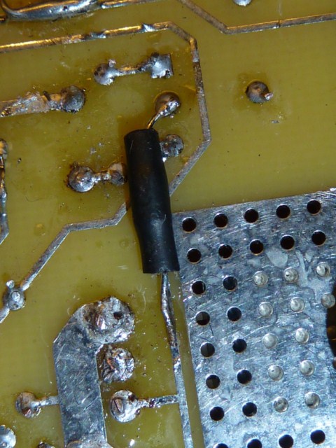
I elected to mount the diode on the underside of the board. The diode leg had just enough room to fit in with the FET leg, which made it nice and straightforward to double up the two jobs.
[EDIT] Corrected as per Richard's suggestion in the following post. It goes to the
gate not the source

. I moved it across to the rail serving the gate (shown at the bottom of the picture).
The other end just went to the bottom of the middle pin of Q2.
[EDIT] Photo of corrected layout as per Richard's suggestion
It'll be some time before I know for sure that this works. I'm still fine-tuning the charger voltage and EOC. It seems that unless I have it just a bit lower than the 86.4V ideal (3.6V per cell), then it sometimes sticks and never switches off. The voltage seems to fluctuate a little according to various factors, and if it goes over a certain threshold then it will just run away, never turning off and just getting hotter and hotter. It looks to me that - for whatever reason - a slightly lowered voltage is what my system is happiest with. All the cells end up nicely balanced once they've settled, and they all discharge in step with one another right up until they cliff-dive at the end.
I've set to see if this mod has fixed the pulse mode yet. One thing I did notice while tinkering, is that once I ramped up the voltage again, pulse mode came on by itself. Is this a good way of 'forcing' it to see if it works, and also calibrating the EOC with this mode?