Zero-Draw, Solid State Contactor w/Precharge (Arduino)

If its ford, it looks like an older FE, not a windsor, cause the bellhousing mating surface near the top is curved on a windsor. It doesn't have the bellhousing bolt in the top middle like the 460/351C, but could be anything.
 
That fossil rock is probably worth something. Also be on the lookout for whale vomit. It's worth a fortune!
http://www.huffingtonpost.com/2012/08/28/charlie-naysmith-whale-vomit_n_1837241.html


The problem of driving a FET gate from 3v turns out to be a real PITA if you want low drain. You'd think there would be a chip that does that. I ran into the same issue wanting to use the MAX11081 chip. It has a 3v output. Standard approach is to make a level shifter out of a pair of transistors.

A cmos comparator (op amp) could work as a level shifter but you need a steady voltage reference of something like 1.5v to feed one input. A plain old diode biased by a 4.7M or 10M resistor might work for that. TLV3701 TLV3702 are examples of the cmos comparators.

My favorite gate driver, the TPS2811 or TPS2812 could then be driven directly from the comparator. Sucks 2uA if you don't use the internal voltage regulator.

The stupid diode/pull up resistor take almost as much power as the rest, but the whole mess would be like 5uA plus stray leakages.

No matter what, you really need a resistor from the FET gates to ground to make sure it stays off when the battery dies. It can be a really high resistance, but something. I'd suggest 4.7M.
 
Arlo1 said:
EDIT: not sure how to make pics work in my quotes but you say "this is the future"?

You're totaly the kind of guy to say something like that when it could be just BS and you like to make simple folk like me wonder WTF is that?

I was speaking metaphorically.... or rather dreaming I guess. I see a future where we are surrounded by the rusting hulks of forgotten combustion engines. Kids will be asking their parents "What? People really used contained explosions to propel heavy steel pods around? Why didn't they just use unobtanium?"

We can then watch the movie: "Who killed the gasoline car?

Hopefully we will be in that movie.

-methods
 
methods said:
Hopefully we will be in that movie.

-methods
I'D love to be in that movie. Maybe a mad max kind of thing where I'm ripping on my 300hp Zero with a mace smashing windshields and bellowing out weird cheetah like screams!
No wait thats the bad guy.... Im more wonting to be Mad max him self! :)
 
Ok - I drank a Bubble Tea, ate a bagel, and decided that I dont have to switch the mosfets on and off fast :mrgreen: Any ol' OpAmp will do unless I can find better/cheaper/easier.

Plan is to put a 50A inductor inline with the HVC Charge breaker and the LVC controller regulator turn-off units. Called up Luke on the phone to talk about slow mosfet switching & using an inductor. He lamented for 30 minutes about the benefits of running an inductor inline - it was enough to convince me to put an inductor into the design. Same thing he told me last week - but I am a hard headed bastard and sometimes it takes 3 or 7 days for me to accept an idea like that.

This will buy us quite a few things... we wont be so sensitive to capacitive loads, PWM will again be an option (slow PMW), and I can still keep my quiescent currents in the dirt (i.e. no fancy mosfet gate driver needed)

So now I am on the hunt for a tiny inductor capable of 20A to 50A.
Voltage switch range will be 10V to 150V
Current will be from 0A to 50A (I can come down on that 50A a touch...)
Source/Loads will be: Charger into battery, Battery into Controller regulator, Or whatever else a user can come up with.

So... if this works out I think I have everything lined up for a prototype.
I already started it - post below.

-methods
 
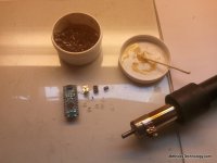
This is an Arduino Nano 3.0
It used to be the most awesome Arduino (though they are old news now)

2013-03-12 15.14.46.jpg
2013-03-12 15.14.56.jpg

Ok - so this is how I like to prototype - Hack Style. First step is to remove everything we dont need using flux and a hot air gun

2013-03-12 16.42.24.jpg


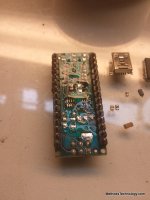
I removed the 4 status LED's, the FTDI chip, its two caps, and the reset cap. I removed the USB Mini plug. Removed the 5V regulator and its tant cap and ceramic cap. Removed the resistor arrays and removed the OR'ing diode that allows use of external 5V or USB 5V.

Ahh... much better
2013-03-12 16.42.34.jpg
2013-03-12 16.43.00.jpg

Now all that is left is just:

On the top
328P Processor
Oscillator (Chrystal with two caps in one unit)
reset button

On the bottom
Bypass cap for the 328P

Thats it man... 3 critical parts and one optional. All you need is a processor, oscillator, and a bypass cap. The reset button could have gone - but it can be useful for testing.

2013-03-12 16.42.50.jpg

Now we are going to upload some real serious power saving code and see if it really will do what the datasheet says it will. (it will, but we always start from a baseline). Then we are going to slowly transition into our design....

* We will start to power from a 3.0V supply
* We will build the 9V charge pump
* We will build up a little mosfet stage (and instrument it)

Luke suggested getting a baseline on the switching noise - so I will find the shittiest supply I have around here and crank it up to 150V and 20A. I will then grab one of my Emoli test packs (25S12P With one bad bank). I will wire in a tiny shunt (dependent on the resolution of whatever scope I can get working - either mine or Lukes) and get some idea of what we are switching. Switch it hard, switch it soft... then we will poke that inductor in there and see the magic happen.

I was planning on running a single diode to freewheel the inductor - but Luke pointed out that it will never see more than a fraction of the switched voltage - so I can run a bi-directional TVS on there and kill shit both ways. Sounds reasonable to me.

Edit: Now I am questioning that... if I run a 2-way TVS and a big noise spike comes it will just forward bias the TVS and bypass the inductor. No way man... we can only run a 1-way TVS - cathode toward the Source.

right?

As the rate of change at the input gets super fast that inductor is going to look like high impedance - so voltage will spike and bias the TVS.


I will be running the inductor on the downstream side.

Here we go...

-methods
 
Yikes! look at how tiny those parts are! I love hacking....

A TLV3701/2 switches pretty fast, just doesn't have a lot of current. I think you could drive gates directly with one, but it would be nice to put a scope on it and see exactly what the switching times look like when driving 4P gates. Since the 3701 is a comparator, the output is either on or off, not much in between. I think you can safely drive a short with one too, so no need for gate resistors.

Yes, and inductor solves many issues, but man, they can be expensive in that current range. It ususally means you need a hefty diode to go with it too.
Any idea how much inductance you need?
 
fechter said:
Yes, and inductor solves many issues, but man, they can be expensive in that current range. It ususally means you need a hefty diode to go with it too.
Any idea how much inductance you need?

As much as I can afford and fit!
I suspect it will be very little...

I have no control over my source and not control over my load - so basically I am just winging it. I can do some worst case tests - but... I never liked designing to worst case... it results in products that never get produced.

Hmm..... Note that I red-lined what I said above. I need to think some more about using a one way or two way diode.

Yea - cost - this would not be the first time Luke convinced me to do some shit that was totally unrealizable in the real world of back-woods budgets :lol: All the time he comes over and shows me some fet and tells me they are like $9... I get all excited and find out they are more like $29 :x But - that is just because I cant buy 100,000 of them (yet). :wink:

Yea - I have no idea what one of these costs, what the inductance range is, what the form factor is, how robust they will be, how big they are, what power range diode I will need... But F-it. I like the idea of having a phat diode inline... if for no other reason than I have never done it before.

-methods
 
fechter said:
A TLV3701/2 switches pretty fast, just doesn't have a lot of current.

Thanks - I will give this one a good looking over DATASHEET

-methods
 
I am toying with the idea of bringing out the internal 1.1V reference from the 328P to bias the comparator.... somewhat dangerous.... Alternately I can add one more part and put down a three pin precision reference. Yea - I realize that a voltage divider is cheaper - but that is two parts to place instead of 1.

The only thing stopping me from bringing out the reference is that I dont know how it will behave when we lose power

new subject

I need to dig through that comparator datasheet and see how it will behave as we lose power. That is the nice thing about gate drivers... is that they are pretty fail safe.

-methods
 
The voltage comparators I know have open colector output, therefore they will be left with a pull-up when powered down.
 
parabellum said:
Cool project, definitively a missing link! It is getting more complicated every day I hope it will be affordable at the end.

It is actually getting cheaper.
The first version I am going to release is just going to be a small PCB board with two pcs IRFB4110. Similar to my original HVC Breaker, a lot simpler and more reliable. I think I will be able to sell them for less - but I have to add up parts and labor.

-methods
 
Njay said:
The voltage comparators I know have open colector output, therefore they will be left with a pull-up when powered down.

Thanks
I will look at the datasheet.

-methods
 
This took me all frucking day.....

2013-03-13 16.06.04.jpg

That is my arduino running in sleep mode. Close enough - gotta go to sign language class now.


-methods
 
Long frustrating day....

Made some progress and made a few decisions.
Someone a while back asked me why I was not using a smaller Arduino - GOOD QUESTION. I am switching to an ATtiny85. It is the smallest pin count Arduino compatible chip - 8 pins.

http://www.atmel.com/devices/attiny85.aspx

Much better package for hand assembly...

banner_tinyavr.jpg


I also toggled back and forth over using 3 x 3V cells or building the booster. I decided on building the booster - but it kind of sucks. Needs work... but I got it working.

2013-03-14 17.31.17.jpg
2013-03-14 17.31.26.jpg

I am using some 100V Schotky diodes that have only a 200mV forward voltage. Using some 0.1uF caps for the pump - then 4uF on the output. Maybe it just needs to be tuned - or have an ass-load more capacitance - but it was super sensitive to load - as in even my fingers :shock:

Whatever - that was just the first indication that it is even possible (other than on paper). Going to go fret about it some more.

I realized once again what the purpose of all this is - to make something - fast - that is easy to assemble - that is reliable - that is cheap - that works - that people like... does not matter if the circuit is cool or lame - only a few people will even look at it - and of those fewer will even care or understand... what is important is that I GET IT DONE and get people a switch that they can use for breaking HVC and LVC.

Sigh... At least Junior learned a new trick today.

2013-03-14 11.18.44.jpg

That's my boy....

-methods
 
Sign language class what? Who's deaf - your daughter?


methods said:
gotta go to sign language class now.


-methods
 
chroot said:
Sign language class what? Who's deaf - your daughter?

Na - my son is not deaf.

Children can communicate way before they have the motor skills to operate their mouth - learning sign language and teaching it to them at a very young age (6mo) eliminates all the frustration and misunderstandings. Simple words like MILK, ALL DONE, SLEEPY

It is not conversational sign language, but rather ASL signs used in an English context. I was not aware until Wednesday that the grammatical structure of ASL for the deaf is totally different than English... now I understand why it is so hard for deaf folks to communicate via text with English speakers!

People should definitely know this... but they dont. I believe that most people think Sign Language is just English spoken with hand symbols - but that is not really the case at all right? The grammatical structure is very different as I understand it.

-methods
 
I had my heart broken tonight :cry:
I fell in love with what I thought was my dream gate driver.....

Logic input
3V supply
Internal charge pump to >7V
Dual input and output
3uA standby current (both inputs logic low)
80uA run current (that will give me a year on a 47mA 20mm coin if used 2hrs a day)

I was gushing. My panties were wet. I was ready to be taken.....

Then things got all weird :?
I was carefully inspecting every table and graph...

See I am going to drive a pair of IRFB4115 fets. I will rate the device at 50A and I have almost no heat sink.... There will be no switching, but I will be turning on with a 150V 50A power supply on one side and a battery load of some sort on the other....

So I get to the gate timing info... and it is in hundreds of uS :eek:
wtfruk?

All the pictures show like 50K resistors inline with the gate :shock:

I stepped into some sort of weird twilight zone of gate drivers. I am so sad..... I thought we were going to make babies together. It was in a perfect SOT-8 package - no external parts needed (not even caps) - it was a dream come true!

http://www.datasheetcatalog.org/datasheets/228/48007_DS.pdf

[Bob and Narrator are in an embrace]

Narrator: [voice over] Bob loved me because he thought my testicles were removed too. Being there, pressed against his tits, ready to cry. This was my vacation... and she ruined everything.

[Marla Singer enters, smoking]

-methods
 
If you just need to turn on once with no PWM ever, and that load switching is always happening always when its unloaded, even if it has no caps to stabilise it, the ground planes could just reference the same point and it can tolerate switching even 300A or whatever in big jerky EV loads with no issues. Its because even though its bouncy all over the place and it has no current handling ability to drive it up or down, it doesn't matter, because the legs are referencing the same spot, so even with a 50kOhm gate drive resistor, its just proportional to the gate drive current its proportional to handle. This gate driver is just capable of pulling very tiny gates up and down at a reasonable speed, or even driving very large gates if the switching only needs to be one saturation. :) You can look on the data sheet and get the safe/destruction energy rate graphs and calculate how long your thing is gonna be in the transitional period for. If its just one switching that is under minimal load while switching, you can use amazing little gate drivers like that be amazing. :)
 
We will be switching a 150V power supply set to 50A into dead 35S pack - so 105V - so only a 45V delta but going into a 20Ah NanoTek it could be a significant amount of inrush current before the supply stabilizes.

Would it work? Yea probably.... but for this design I want it to "work by design" instead of "work by luck and margin" :)

I am going to take the work done on this HVC breaker and apply it to the SSR.

Hmmmm... I wonder what the inrush currents will look like with a small inductor inline....

-methods
 
methods said:
Hmmmm... I wonder what the inrush currents will look like with a small inductor inline....


It's so cool switching with a decent amount of inductance in a circuit. Your in-rush switching has virtually zero current flowing for the first rising edge, it's like getting to to make unloaded while the inductors core is still growing it's field before it saturates and passes DC.
 
You think I can get away with 100uS switching times if I have a phat inductor inline with the power mosfet? IDK... 1uH 50A goes for about $3 and I have no feel for how much that will change the current profile given all the other variables. All of the data sheets gloss over the fact that the inductors burn 2-4W of power too in a package that is way too small (i.e. temps are going to go through the roof). These are surface mount - I suppose I need to go dig for some wound inductors - but that too will greatly increase costs. Something like $10 is a complete non-starter for a project like this - and we are buying in 10pcs quantities.

I really have no feel for this as most of my testing and experience has been either utilizing a top-shelf 7A gate driver (no concern for waste power) or utilizing either Latching Relays or caps to drive the power mosfets (in my sub 100uA circuit) - on my last circuit I was pulling up the gate with 4.7M but in parallel I had a good size cap - so turn on was very strong - and turn off was accomplished with a relay contact closing.

I am at my wits end searching for a solution to have a 3V uController drive a 7V Mosfet gate while not breaking the bank on Quiescent draw. I think I have no choice but to limit inrush current with inductance and drive the mosfet gate a little slower.

-methods
 
Maybe I need to go back and review the solutions I already eliminated. One thing I have not looked into is the OpAmp with the Totempole on the output. I cant remember how much bias current those eat up. I would really like to do a mosfet totem - maybe that is what I will look at next

Damn... I went from a simple 5V uController that was driving a 100V logic gate mosfet... to a frigging nightmare

3V supply
Anything over that will be from a DC-DC or pump
Budget of 100uA absolute max for the entire circuit
Need to switch a pair of IRFB4115 mosfets - get the gates to over 7V relatively fast (whatever that really means)
Bastards bastards

So many parts look good on the data sheet but when you start digging hard they all draw way more than the implied low current - either through excessive logic input current (pull downs) or datasheet tricks for the supply voltage or whatever - ugh

Thinking I may have to totally re-think this.

Going to go look at totempole packages... I just hate BJT's :evil: I really dont like using current controlled devices - almost as much as I dont like inductors.

-methods
 
Back
Top