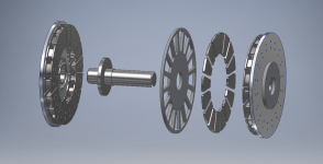
APL's DIY axial-flux motor

The support ring for the cores should go all the way to the outer edge for the most support. If the support ring was fairly thick aluminum, it could be used to carry heat away from the cores if it was attached to the housing. Water cooling could even be done by having channels or tubes on the support ring.

The magnet forces on the cores will be pretty extreme and a collision when assembling could easily crack a core.

If the cores were wound and then saturated with epoxy, the copper would add quite a bit of strength.

If the holes in the cores are counter bored so the screw heads are down a ways from the face, the flux will tend to go around the hole and minimize eddy currents in the screws. Non magnetic stainless or titanium should be good. If the cores are aligned on both sides, you might have an issue with the screws not having enough threads engaged. A nut on one side might work, but nuts will take a really big hole. One option would be to offset the cores from one side to the other so the screws can avoid each other. The rotors would need to be offset by the same amount so the phasing is the same on both sides.
 
fechter said:
The support ring for the cores should go all the way to the outer edge for the most support. If the support ring was fairly thick aluminum, it could be used to carry heat away from the cores if it was attached to the housing. Water cooling could even be done by having channels or tubes on the support ring.

The magnet forces on the cores will be pretty extreme and a collision when assembling could easily crack a core.

If the cores were wound and then saturated with epoxy, the copper would add quite a bit of strength.

If the holes in the cores are counter bored so the screw heads are down a ways from the face, the flux will tend to go around the hole and minimize eddy currents in the screws. Non magnetic stainless or titanium should be good. If the cores are aligned on both sides, you might have an issue with the screws not having enough threads engaged. A nut on one side might work, but nuts will take a really big hole. One option would be to offset the cores from one side to the other so the screws can avoid each other. The rotors would need to be offset by the same amount so the phasing is the same on both sides.
The support ring must be magnetic, otherwise it would add impedance to the magnetic circuit. Flux need to go from one magnet through the first core, trough the ring then the other core and the opposing polarity magnet.
I dont like the use of screw on the closest face to the magnet, it will surelly add massive losses and heat up fast. Having a non laminated center ring is okay tough since it's far away from the moving magnetic flux.
I see it more like the drawing APL did few posts ago with some kind of radial flange


Envoyé de mon Redmi Note 3 en utilisant Tapatalk

 
Thecoco974 said:
Flux need to go from one magnet through the first core, trough the ring then the other core and the opposing polarity magnet.

If the cores are touching each other on the side away from the rotor, all the flux will pass to the adjacent cores instead of through the support ring. The support ring will have essentially zero flux, so can be any material.

Having a single core that goes from one rotor to the other rotor would also work but supporting the cores would be difficult. If you could find a good way to support the cores, you could use less core material and save some weight and loss.

I'm not so sure about having screws in the pole face. If the screw head is close to the rotor magnets, there will be some big eddy currents in the head. If the screw heads are recessed enough, the flux takes the path of least resistance, which would be around the hole and away from the screw, so would minimize eddy currents. A MFEA model would be good to see if this is true.
 
There are several kids of fasteners that are probably available if we look around, I'm sure I haven't seen them all,.. but
recessing a fastener down into the tooth is probably a good idea. Could even maybe plug it, if it could be removed easily.
(and not sucked out by the magnets)

I was thinking maybe a center threaded tube-nut of some sort, and a screw from both sides, that goes all the way through
the support ring. Rivets? Anyway,.. keep thinking, we'll find it.

I like the idea of bonding the wire to the cores for strength,.. makes sense. It would be nice to find a solvent that would
remove it for a re-wind. Otherwise, new cores. Depends on what they will cost.
Yes, I have some concerns about whacking them with the rotors. Some sort of outer protector would be nice,.. as much
as I hate the idea. But installing rotors can get rough some times. Maybe something that can be removed after assembly.

I was able to weigh the old stator plates, and they came out to 712 grams for the pair. Then I took the back iron off a rotor,
which would be about the same size as a support ring in steel, (1/8" thick), give or take, and it weighed 674 G. with magnets.
After subtracting magnet weight, it came out to 424 grams.

So a single steel center support ring is a lot lighter than two plates.

But now you just said that it doesn't have to be steel? It can be aluminum? :!: Yikes!

Yes I can see where each side has it's own back iron. Would we wire the two sides as if they were one core going all the
way through, or would we wire the two sides in three phase, and hook them together in parallel? Guess I'm not thinking
clearly on it. Probably the same either way.

But an aluminum center support ring is getting me pumped! Are you sure? :confused:
 
I'll respond to the last several posts later, but I think the cores can reasonably be tapped and screwed from behind. I'll do a test and see what kind of force a 10-32 thread can take in the #40 before failure. In general, it is actually a little less brittle than I expected. I don't think there will be strength issues with larger cross sections.
 
That would be good, screw through to the other side. No nut.

Fechter, I see what you mean now by offsetting the cores too. Since they are two separate circuits on each side. I keep
thinking in terms of symmetry, but the rotors would be balanced, even if the cores were shifted. And that means, yes,
you could do a six phase. Although, I'm not sure how the controller(s) would be set up. :?:
Interesting stuff.

An aluminum suport ring could be water cooled, you are right. In a simpler version, maybe a little heat sink material all
the way around. (not really much room though, in a 8" stator, 9.5" motor.)

If they are two different magnetic circuits, then the aluminum ring can be made as wide as wanted, for various cooling
ideas. But this particular motor needs to be as thin as possible, for spoke angles. Spokes can come off of the rotors, or
off of the bearing caps. Caps are better, as longer spokes will work normal, and theres no stress on the rotors, but then
the motor width is important, for spoke clearance to the outside of the rotors.
Sorry for getting ahead of things.
 
fechter said:
Thecoco974 said:
Flux need to go from one magnet through the first core, trough the ring then the other core and the opposing polarity magnet.

If the cores are touching each other on the side away from the rotor, all the flux will pass to the adjacent cores instead of through the support ring. The support ring will have essentially zero flux, so can be any material.

Having a single core that goes from one rotor to the other rotor would also work but supporting the cores would be difficult. If you could find a good way to support the cores, you could use less core material and save some weight and loss.

I'm not so sure about having screws in the pole face. If the screw head is close to the rotor magnets, there will be some big eddy currents in the head. If the screw heads are recessed enough, the flux takes the path of least resistance, which would be around the hole and away from the screw, so would minimize eddy currents. A MFEA model would be good to see if this is true.
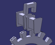
Sorry I think i haven't really understand how the core are sustain and where goes the ring. For my idea here is a rough modeling of it :idea.PNG
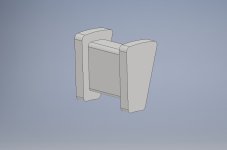
The core is the dimension given by APL, they might be hard to machine but they are one piece, so more integrity and a better flux pass i guess.
I may try for the screw on femm, but in any case if they are recess that mean a wider air gap over it.
 
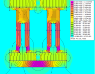
Actually you were right Fechter, if the screw head is sufficiently buried flux wont go much trough it : screw_flux.PNG
Here the simulation is with N52 magnet (20x5mm), 5mm screw heads ans 4mm body, 20mm wide core face, and 10mm wide core.
I might have made it too narrow, but it shows that depending on srew size and core width, saturation is possible. (by the way core material is pure iron, screw is inox 316)
 
APL, can you please tell why do you want to throw away your first design? i mean why can't you build it like this:
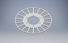
make a two stator plates like at picture below from fiberglass (5 mm tickness):
stator plate.jpg

with SMC core like you want (i think you could use even simplier design):

SMC core.jpg

and make aluminium hub like this one:

hub.jpg

the assemply looks like this:

stator assembly.png

sorry i was to lazy to put all the smc cores in the picture but i guess you got what i mean.
 
Wow, you guys are really doing a lot of work! :thumb:

This is really good stuff, and I wish I could reply in detail, but I'm totally out of time this morning, and have to run.
Busy day today.. Just my luck. :( I'll get back to it this eve.
 
Nice work Thecoco974, thanks for the simulation, thats awesome! So many good ideas coming up here, and you've shown
one more great idea. :thumb:

Each core comes out easily, and the U clamp holds them tight, and shoves the back iron flanges together solid.
A little shim stock on the bottoms, would space them just right.
Theres extra material in between the cores for the clamp, but not that much, could probably get by with 7-8mm wide
stator ring.
Lost the screws in the cores, which is really nice not having holes.

The back flanges on the cores will still have to touch each other, in the same way that we've been discussing, or else the
U clamps would act as a 'one turn' short, just like what happened on my motor, before I cut the stator plates.
(I think)

Other than that, I guess it comes down to how much harder it is to machine the cores that way, and maybe the extra
machining for the U clamps? Definitely a viable plan.

Damirsky, I really need to learn how to do cad drawings, thats mighty fine! The fact is, that it could be done that way,
but you'd have to bond some .032" G10 Garlite board to the faces to strengthen the stator fingers, which are quite thin.
And keep the cores from moving, otherwise you have to hold the cores some how as well.

Even then though, the plates would be weak, (side to side), and if you wanted to keep a close gap between core teeth,
(2-3 mm), you couldn't do it. In fact I don't think that 5mm fingers would be strong enough either, and when you get up
towards 10mm wide fingers then you've lost a lot of tooth area. 17cm on 18 teeth.

The two stator plates also tend to hold in heat, and make the cooling a little more difficult, and one of them has to be
taken off, before you can get to the wiring, which has less space,.. because of the two plates.
Just saying.
It could be done, but having a single center flange and ring to hold the cores can be made solid, more cooling, more
space, and less machining. Maybe even lighter.

Anyway, thats why I'm leaning in this direction, I think it's stronger lighter, and easier to make.
 
APL said:
....
Damirsky, I really need to learn how to do cad drawings, thats mighty fine! The fact is, that it could be done that way,
....

Tinkercad seems to be very popular, works in a browser so no need to install anything. I use librecad (open source, based on qcad) for most things, used it for years and it works great for me but it's a bit primitive these days, still much quicker than even rough sketches by hand though (snap to grid, endpoints etc. are the big time savers).

Finally got some time to get to grips with FEMM, fairly easy to use and has been a total game changer. Entering all the details (materials, circuits etc.) can be a bit laborious as can the built in drawing functions for anything more than really basic sketches (.dxf import ftw) but it's well worth it, shows at a glance what would have taken hours of calculations or years of experimentation without it.

Did you get any rust on the bonded material yet? I'd imagine it rusts, could mean some sort of coating is essential.
 
APL said:
Damirsky, I really need to learn how to do cad drawings, thats mighty fine! The fact is, that it could be done that way,
but you'd have to bond some .032" G10 Garlite board to the faces to strengthen the stator fingers, which are quite thin.
And keep the cores from moving, otherwise you have to hold the cores some how as well.

Even then though, the plates would be weak, (side to side), and if you wanted to keep a close gap between core teeth,
(2-3 mm), you couldn't do it. In fact I don't think that 5mm fingers would be strong enough either, and when you get up
towards 10mm wide fingers then you've lost a lot of tooth area. 17cm on 18 teeth.

The two stator plates also tend to hold in heat, and make the cooling a little more difficult, and one of them has to be
taken off, before you can get to the wiring, which has less space,.. because of the two plates.
Just saying.
It could be done, but having a single center flange and ring to hold the cores can be made solid, more cooling, more
space, and less machining. Maybe even lighter.

Anyway, thats why I'm leaning in this direction, I think it's stronger lighter, and easier to make.

sorry, i'm not agree with you that 6 mm (not 5 mm, btw) fingers would be weak. please take into account that fingers are connected to outer and inner rings of the plate. another point is that the smc cores will be glued inside of the milled slots and this will add some rigidity to all the fingers.
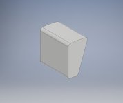
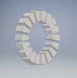
if you don't mind, i would suggest you to make smc core shape simplier. like this one (height is 35 mm):
SMC core #2.jpg
making core like this will save you expensive smc material and labor for cnc machining. please also look at the axial flux stator fechter showed us few times:
file.php

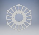
you see there is plenty of space between teeths, not a 2-3 mm. if you choose cores like at picture above, the stator plate could be like this one:
stator plate #2.jpg
as you can see the distance between smc cores is 8 mm. 18 pcs of cores with slot width of 8mm looks like this:
18 pcs SMC core #2.jpg
it is just smc cores with no copper. you can make magnet wiring from copper foil. insulation could be made by capton film or by some high temp enamels.
the stator assembly looks like this one:
stator assembly #2.jpg
it is just an example, you can make outer case made of bonded aluminium sheet or may be some other variant.
 
APL, I see the one turn short too and it need to be taken out of course. Like you said one way is by making the plate electricaly and magneticaly in the same circuit by using magnetic materiel and having an electrical contact between the disk and the core, but that way it make the magnetic circuit of different tooth shorted together, it might be beneficial or causes problem, not sure yet (FEMM study needed i guess).
The other way is by opening the loop like you did on your first build, using a non conductive material between the U shape and the disk and a non conductive washer on the screw might be good enough. Using this technique you can keep your signature beautiful anodizing on those part making them lighter as well (no need for magnetic material) !

Damirsky, I think that those simplified cores are a lot easier to manufacture, but the good balance of core area/Winding space need to be figured out. Having such a large area make the saturation nearly impossible but leave a lot less room for copper fill and thus it's also dead weigh. To make this motor Power/weigh ratio the best it can we need to find the minimal core dimension with no saturation. I'll try things on FEMM, but since it's a trapezoidal shape i'm not sure on how to do it yet.
 
Thanks stan.distortion, I'll try looking those up, I need suggestions like that to get going, as I'm in the dark at the moment.
I have to start with graphics if I want to do 3D., and CNC ready stuff. No rest for the old man.

Thecoco974, those U clamps could be made of composite, and there wouldn't be any 1T short, I think.
I'm still not sure which is better, steel, or an aluminum ring,.. but we can try both, they're bolt on's.

We still have to hone in on the best amount of core material Lebowski, for sure. We need to have the magnets and a
temporary core first, in order to figure that out. We have to start someplace,.. like fechter says, look at what other motors
are doing first, and copy it to get started. Unless you have a good way to figure it out that we can use?

Thats looking better damirsky, nothing wrong with running no-tooth overhang, it gives you more spacing, and less weight.
You loose some area on the teeth and magnets though, that might give the motor more power.
I like the overhang though for retaining the coil wire, and it's just a mater of adding it to the CNC program, so it's a double
win. Most actual motors I see have tooth overhang, or profile of some sort, I not sure what that stator ring is from.

Gluing the cores to the tooth would work fine,.. but it's something that I'm trying to avoid, because it makes the motor
permanent, and I would really like to have it so a person can rewind the coils and change things out.
So there needs to be another way of holding the cores, which is why I was going to bond the .032" glass board to the faces.

You added spacers and eyelet's to the outside of the diameter, which is nice, there could be more of them.
Problem is with the rotor spacers though, which take up that area, and in order to clear the eyelet's you would need a
larger diameter motor. Which can be done. But, if you are trying to stay under 9.5" like I am, then you loose a lot of torque,
since the cores will now be much closer to the axle.
One of the benefits of the center ring design is that the cores can be moved all the way to the outer edge of the stator.

I don't have a problem with what you've done, you have some really great ideas going on there, and impressive. But I
still think the center ring idea is better so far.
That could change though, it might run into problems yet, and I'll be back to looking at your direction again.
Apparently, motor design is a back and forth thing.
 
It's time to get the axle and bearings drawn in, at least as best as I can figure for the moment. I didn't make thing's very
precise, as I'm sure things will change soon, but at least we have something to look at and point to for the moment.

Not as nice as your cad renderings though. Hope you can tell whats going on. :)

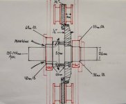
There are three main pieces,.. the axle, the adapter ring, and the core support ring.
The adapter ring and axle could be made as one piece, but there would be lots of waste.
And two piece allows for centering different outer rings.

The axle is made out of 2" aluminum stock, with less wasted material. The adapter ring thats bolted to that, is 1/2" flat
stock, cheap and easy, with lots of holes drilled into it, for air and wires.
The core support ring is 1/4" aluminum, or 1/8" steel, and is pretty straight forward. If you use tool steel for a ring, it
could maybe be thinner, but more expensive.

I put the middle adapter ring close to the drive bearing side, on the right, for strength with the gears.

Axle and addaptor ring..jpg

Nothing set in stone of course, just putting ideas in a group, feel free to make suggestions.
 
APL said:
Thecoco974, those U clamps could be made of composite, and there wouldn't be any 1T short, I think.
I'm still not sure which is better, steel, or an aluminum ring,.. but we can try both, they're bolt on's.

Yes they can be made with composite, but aluminium would give better heatsinking capabilities. Steel vs aluminium is only a design choice I think, might impact weight, but nothing else than I can see.

Your drawing is looking great, as always !
About the adapter ring why not making only one going from the cores to the axle ? doing it this way will add weight, it's not rotational mass so it's not that important but making it as light as possible is still great :) .
If you keep this idea though you may want to add a shoulder on the adapter ring for centering the outer ring.
 
APL said:
It's time to get the axle and bearings drawn in, at least as best as I can figure for the moment. I didn't make thing's very
precise, as I'm sure things will change soon, but at least we have something to look at and point to for the moment.

Not as nice as your cad renderings though. Hope you can tell whats going on. :)
here we go..
APL's design axial flux motor.jpg
There are three main pieces,.. the axle, the adapter ring, and the core support ring.
The adapter ring and axle could be made as one piece, but there would be lots of waste.
And two piece allows for centering different outer rings.

The axle is made out of 2" aluminum stock, with less wasted material. The adapter ring thats bolted to that, is 1/2" flat
stock, cheap and easy, with lots of holes drilled into it, for air and wires.
The core support ring is 1/4" aluminum, or 1/8" steel, and is pretty straight forward. If you use tool steel for a ring, it
could maybe be thinner, but more expensive.
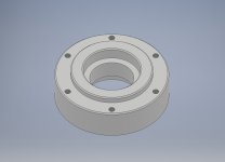
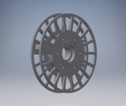
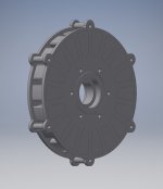
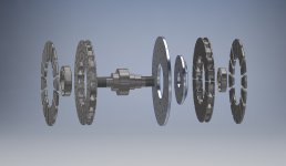
i did it with sizes you mentioned at your drawing and used my imagination:
- motor config is 18/16 as you mentioned
- magnets tickness is 5 mm
- cores support ring outer diameter is 200 mm
- axle length is 130 mm
- approximate weight of the parts shown at the picture is 5.8 kg (no wires, no rotor plates and no ball bearing hubs). i don't know exact dencity of the smc and the magnets so i set it as a steel. also there are no srews..
i think the axle should be made out of stainless steel not an aluminium alloy.. this motor looks like a hub motor (have a closer look at the axle, hehe..). :roll:
I put the middle adapter ring close to the drive bearing side, on the right, for strength with the gears.

Axle and addaptor ring..jpg

Nothing set in stone of course, just putting ideas in a group, feel free to make suggestions.
i'm with Thecoco974 and don't understand why do you need that adapter ring. i think core support ring could be just enough.
finally, just fyi i draw the inrunner axial flux motor with using of the same (almost) parts..
Damirsky2APL design.png
it's a bit lighter (5 kg) and have better cooling capabilities..
p.s. you'll need to make 36 (thirty six!) pcs of that small fancy smc cores.. :)
 
Am I making things up, or should the slot gap be about the same width as the magnet thickness? I feel like I've read that a few places.

Responses to specific posts upcoming:
 
fechter said:
The support ring for the cores should go all the way to the outer edge for the most support. If the support ring was fairly thick aluminum, it could be used to carry heat away from the cores if it was attached to the housing. Water cooling could even be done by having channels or tubes on the support ring.

The magnet forces on the cores will be pretty extreme and a collision when assembling could easily crack a core.

If the cores were wound and then saturated with epoxy, the copper would add quite a bit of strength.


I don't think the material is as fragile as we've been discussing. I won't have time today to do the thread testing, but should be able to tomorrow. I don't see why we need a ring that goes all the way to the outer edge for support. The cores are seeing axial and tangential forces, but minimal radial (component of tangential force only?). I do see merit in having a support ring that can conduct heat away, though.

If we've decided recessed screw heads actually aren't a problem, then that's a more mechanically-sound solution for attaching the cores. Think of the stuff as concrete...It does terribly in tension and bending (without rebar or the like), but really well in compression. Having the screw compress the material instead of my suggestion to thread and screw from the back side leaving most of the material in tension is a good call if there aren't significant magnetic compromises.
 
damirsky said:
if you don't mind, i would suggest you to make smc core shape simplier. like this one (height is 35 mm):
SMC core #2.jpg
making core like this will save you expensive smc material and labor for cnc machining. please also look at the axial flux stator fechter showed us few times:

Cores with no overhangs will be cheaper, but not significantly so. We're still talking two setups and the extra machine time is minimal. Couple American dollars a piece, absolute max...Probably closer to $0.50 a piece. Setup still needs soft jaws, so no time saved there. In general, not a big deal to make overhangs.
 
APL said:
The axle is made out of 2" aluminum stock, with less wasted material. The adapter ring thats bolted to that, is 1/2" flat
stock, cheap and easy, with lots of holes drilled into it, for air and wires.
The core support ring is 1/4" aluminum, or 1/8" steel, and is pretty straight forward. If you use tool steel for a ring, it
could maybe be thinner, but more expensive.

I put the middle adapter ring close to the drive bearing side, on the right, for strength with the gears.

Axle and addaptor ring..jpg

Your drawings are great! No trouble understanding them at all.

On the discussion of CAD software, I wouldn't touch anything on the free/ish market except Fusion 360 (free for hobbyist and businesses up to $100k revenue) or onshape. I strongly recommend Fusion. I use SW, but of course it isn't free.


On the adapter ring, I don't really see the need for one. What's the value of it vs. making the support ring for the cores bolt directly to the shaft? I also don't like the idea of a small diameter shaft in general, but realize that's the standard arrangement for Ebike outrunners.
 
Wow, a lot going on overnight! Damirski, thats just awesome, looks perfect, and you drew the in-runner as well! :thumb:
The two motors need to be developed, as they are the two main styles or types for two different purposes. The Twins.

So nice to see everything in a cad picture, it makes it so much easier to envision things, so we can make changes.
I'm really blown away by the fact that you can approximate weights!

The adaptor ring is unnecessary, for sure, if all three parts are aluminum. I drew it as an idea for different types of rings,
like steel, or carbon fiber, or whatnot, in an attempt to leave the axle alone for each design. And yes, it should have a
sholder, for the next ring to index on, if that set up is used. The axel could recess into it as well.

But a two pice set up is better if they are aluminum. Axle and ring. The axle can still probably loose some material here
and there as things move forward. I chose 2" but it could be larger diameter, whatever you think will be best, feel free to
tweak it. Just remember that we need lots of room for coil wiring in there.

Coleasterling, the shaft size, at least the outer ends, have to be able to fit through a cog (and BB cup for me), on the drive
side anyway. Also, bike dropouts will only allow a certain diameter. (unless I misunderstood your statement)

I don't know about the slot gap question, good point. I guess I'm just going by Fechter's statement "no less than 2mm",
between teeth, and from what I see in other motors. I assume that a person wants as much tooth area as he can get.
But that may be unfounded. :?:

You're the second person in the industry that has suggested Fusion 360 to me. I'll probably check that out,.. what I don't
want to do is zig-zag between different programs to get to the one I should have started out with.

Lots to respond to, hope I didn't leave anything out. :D
 
Back
Top