
You don’t want a sheet of lamination iron on the face of the core. This would have a major eddy current. Any laminations need to be parallel to the flux direction.
You are using an out of date browser. It may not display this or other websites correctly.
You should upgrade or use an alternative browser.
You should upgrade or use an alternative browser.
APL's DIY axial-flux motor
- Thread starter APL
- Start date
InterestedinEVs
1 kW
- Joined
- Sep 21, 2010
- Messages
- 309
Well darn, makes sense when you say it.
So maybe instead of steel, use the fiberglass we've been talking about as the face sheets?
So maybe instead of steel, use the fiberglass we've been talking about as the face sheets?
Fiberglass would be ok.
guys, i think we are moving in a wrong direction. if the cores will be made like this:
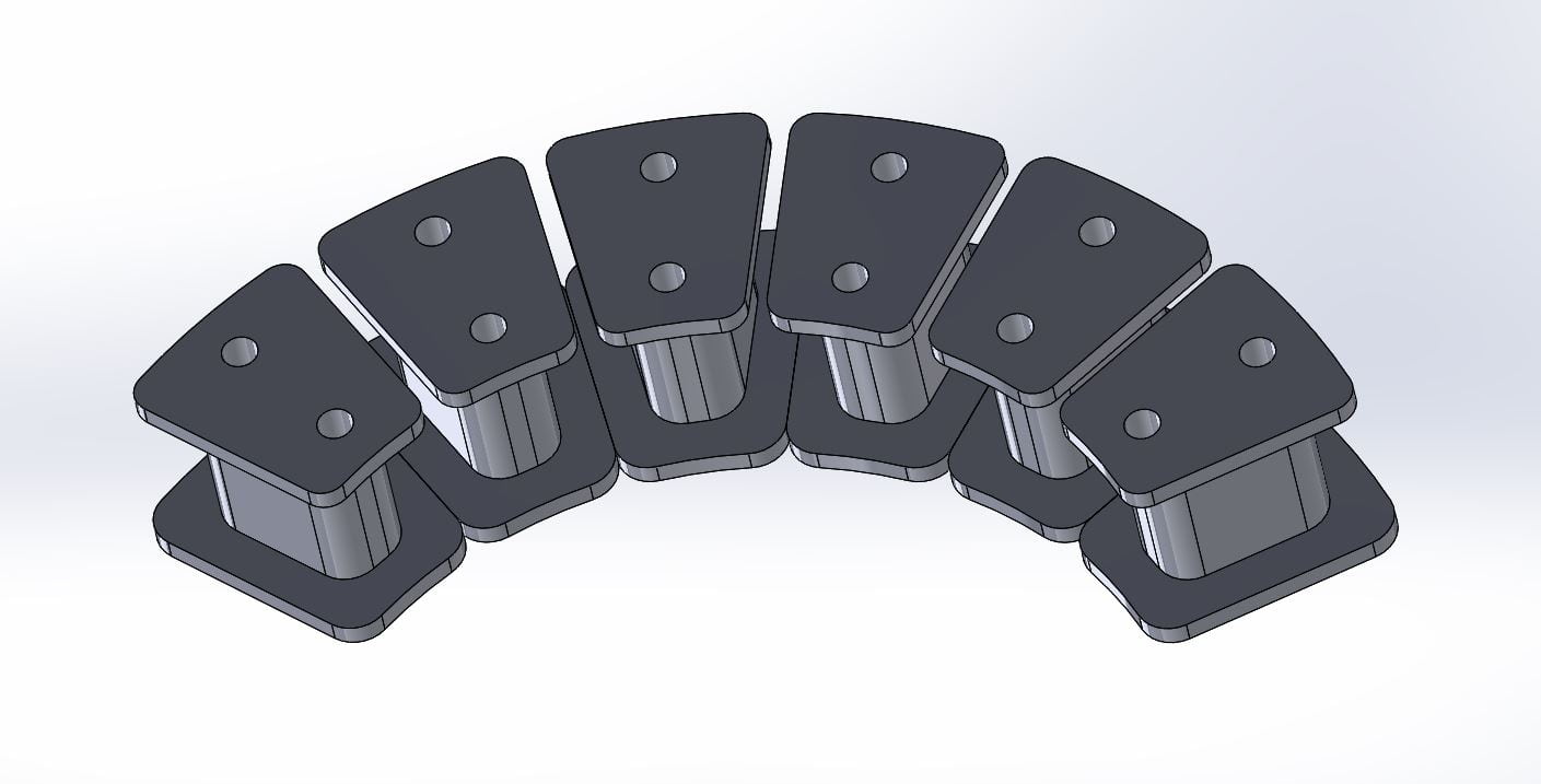
or like this:
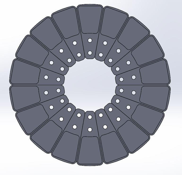
the lower overhangs connected to each other and form the yoke. if the yoke tickness at least 0.8 of teeth's tickness, the cores support ring could be made of aluminium or any other material.
or like this:
the lower overhangs connected to each other and form the yoke. if the yoke tickness at least 0.8 of teeth's tickness, the cores support ring could be made of aluminium or any other material.

stan.distortion
1 kW
- Joined
- Jun 12, 2019
- Messages
- 377
coleasterling said:Nothing to add to the last few posts other than that a more round geometry is easy to do and probably better for stress concentrations on the cores. External sharp corners are generally bad just like internal sharp corners.
The threading test worked well, but I found another issue in that on tightening, the core will crack right through the thread, axially. After that, I don't feel that we can effectively thread and screw into the cores. Bolting through from the outside face might be the only solution. It may make sense to use shoulder screws during assembly to limit bolt clamping on the core, too.
Is there any info on using adhesives with the material? It might be possible to form a chemical weld with the binder, ie. stronger than the composite material. That could open up plenty of mounting options depending on what materials can be bonded to.
APL
100 kW
- Joined
- Aug 6, 2018
- Messages
- 1,113
It probably would be a good idea to bond some fiberglass to the surface of the tooth. I think it goes down to .020".
Just to beef up the overhang a little more.
Maybe think about boding the wire, (enamel?), as well, if it can be removed by soaking. (paint stripper)
It's pretty sure bet that they will be bumped or hit at some point.
I was looking around a little at fasteners this morning, and found some PCB standoffs that might fit the bill. They
come in brass, aluminum, nylon, plastics and steel's.
A 10mm long one between the teeth, and a screw from each side might be enough to hold them, and not break the
SMC.
Maybe some Locktite around the core bases, that can be heated for removal would help too. Or as stan.distortion says,
adhesive's, but I would want to be able to remove it too.
APL
100 kW
- Joined
- Aug 6, 2018
- Messages
- 1,113
Well were up to Rev. 4. On this one I included the G10 Garolite stator disc, the inserted cores, and even threw in
some tentative bearing cap hub flanges, and freewheel mount.
(There's an optional reinforcement ring on the right side of the stator)
Things are looking tight on the disc brake/phase wire interaction, but may work. But not so good on the freewheel side.
If it's going to be a hub motor, it might have to have a standard threaded steel axle through the center of the aluminum.
Most freewheels that I've seen don't have a very big hole in the middle, certainly not 26mm.
I suppose a large torque arm on the left would solve the small axle issues.
The spoke angle as it passes the rotors is questionable too. It will be tight for large rims, but will hit any small ones.
I really don't want to spoke the rotors. All the stresses of the road, and bike, are going to try to mess with the air
gaps that way. I think it's just wrong.
So motor-wise, I think things are looking real good. :thumb:
But Hub motor-wise, not so much. Might have to revert back to Mid-drive only, unless these things can be overcome.
APL
100 kW
- Joined
- Aug 6, 2018
- Messages
- 1,113
After some more thought, I realize that the brake rotor has a specific place on the axle, farther to the left. So that will
move the axle to the right and give the wheel the dish thats needed, and the freewheel gets more room on the right.
Details, details.
Dishing on the right will give more spoke/rotor clearance, and moving the hub flange left will give more on that side too.
I'll have to measure all this stuff up.
move the axle to the right and give the wheel the dish thats needed, and the freewheel gets more room on the right.
Details, details.
Dishing on the right will give more spoke/rotor clearance, and moving the hub flange left will give more on that side too.
I'll have to measure all this stuff up.
APL
100 kW
- Joined
- Aug 6, 2018
- Messages
- 1,113
I've been watching tutorials on Tinkercad and Fusion 360. Tinkercad is a bit basic and I can draw way faster than that,
and since it is unusable in 3D or CNC machines, I don't see the point of investing time in it.
It doesn't look like too much of it would be very familiar in Fusion 360.
Fusion 360 is way more complex, or at least 'can' be. But since it will be usable in 3D and CNC machines, it would be well
worth the time invested. I can still draw and sketch 50 times faster.
Drawing is fun, relaxing, and easy for me, and computer symbols and drop boxes are painful. But I'm sure it will get easier
as I get used to it, and learn the short cuts.
The resulting effort pays off when you watch a machine make the part, or even thousands of parts.
I'll keep plodding forward, thank goodness for tutorials. I really need to get with the 3D printing movement though, since
it is the present and future of things. I'm not sure if the current 3D machines have their own cad programs or not, or if
they will accept Fusion 360 or not, I'm sure that some will.
stan.distortion
1 kW
- Joined
- Jun 12, 2019
- Messages
- 377
APL said:I've been watching tutorials on Tinkercad and Fusion 360. Tinkercad is a bit basic and I can draw way faster than that,
and since it is unusable in 3D or CNC machines, I don't see the point of investing time in it.
It doesn't look like too much of it would be very familiar in Fusion 360.
Fusion 360 is way more complex, or at least 'can' be. But since it will be usable in 3D and CNC machines, it would be well
worth the time invested. I can still draw and sketch 50 times faster.
Drawing is fun, relaxing, and easy for me, and computer symbols and drop boxes are painful. But I'm sure it will get easier
as I get used to it, and learn the short cuts.
The resulting effort pays off when you watch a machine make the part, or even thousands of parts.
I'll keep plodding forward, thank goodness for tutorials. I really need to get with the 3D printing movement though, since
it is the present and future of things. I'm not sure if the current 3D machines have their own cad programs or not, or if
they will accept Fusion 360 or not, I'm sure that some will.
Maybe keep 2d in mind, for extrusions (very common task) it's often easier to draw the 2d shape with 2d cad software and then import it into 3d cad software and 2d is usually much quicker for roughing out ideas. Maybe consider the toolchain (the collection of software used for a task) from the other end as well, what kind of files you need to pass on to the CNC stage. Usually that's gcode for operating the cnc machine or STL files for a 3d object file to send to an engineering company. Both of those are truly horrible file formats btw, gcode is a godawful relic from the 60s and stl's cause almost as many problems as they solve but they're pretty much the industry standards :/ Most engineering companies should be able to handle any common 3d file format but it's worth checking beforehand.
Ultimately it's down to what you get on well with, you'll get far more done with something old or buggy that you're comfortable with than with something top quality that makes you want to pull your hair out. There's plenty of free cad software out there and many commercial packages have trial or limited use offerings, worth trying out as many as possible imho.
Something I use almost exclusively for 3d is OpenSCAD but I'd hesitate to recommend it, it's more like a programming language than a cad program but it's extremely powerful. For example, a parametric motor design would be fairly straight forward, something that's given variables such as speed and torque and scales all the components to fit those criteria. Many other cad packages allow some degree of scripting but it can be a steep learning curve.
InterestedinEVs
1 kW
- Joined
- Sep 21, 2010
- Messages
- 309
As long as the program can export the model as an STL file, pretty much any slicer will make code from it. STL is a horrible format and I'm not sure why it became the go to format for 3D printing. Fusion will export .stl files and I believe even has plugins for slicing in the software.
The real power of a parametric model program is the ability to create solid models that are easily modified without wrecking critical features. Say you have to have a plug that fits into a square hole. The square is 1" x 1", but you don't know the correct radius right off hand. You'd make a 1" x 1" base model, then you can add your radii to the edges that can be changed from, say, 1/16" of an inch to 1/4" with three clicks. Carry that further and you can create an assembly around it that self-propagates the changes to the rest of your whole model, without having to change every mating feature. This is relatively easily done in Fusion. Like say we want to make a motor model, but change how round the core is. We'd model one winding core, pattern it, then when we change one feature, it'll change the whole motor automatically.
I disagree with Stan about importing from a 2d program. Never, ever would I do that. Use the 2D environment in Fusion or SW or whatever other parametric program you want to use. There's absolutely no reason to import 2d data (unless it was drawn in Autocad 20 years ago) and convert to 3D. Parametric modeling is pretty much just drawing a base 2D shape in the 2D environment and giving it depth in the 3D environment. They go hand-in-hand and the transition is pretty seamless. You can draw your 2D features on faces of 3D shapes easily, for example. Just start playing with it. I'd be surprised if you didn't get the hang of Fusion in a couple weeks.
I also don't think there's any reason to use ANY open source parametric modeling software. None are close to as polished as Fusion or Onshape. Neither are going anywhere anytime soon. If you're worried about your data disappearing, build your models and export in a universal format like IGES or STEP. You lose the parametric nature of the model, but at least it is still a solid.
APL
100 kW
- Joined
- Aug 6, 2018
- Messages
- 1,113
Thanks guys, that helps a lot. I didn't know about STL, or anything about how that end works. Sounds like Fusion is
the way to go if it will export it. I'll try to find a free version and download it.
Sketch and draw everything out until there are few changes left to be made, and then create in Fusion and check for
3D interferences, and wala, get parts made. :thumb:
Right now I'm still working on a drawing of the motor with 'real' freewheel and brake measurements, steel axle insert,
and spoke angles. Turns out that every single millimeter is used. I can't seem to make it work under a 140-142mm axle
length. And thats with a 9spd freewheel, which I'm sure 90 percent of hub motors are using, if they're thread on.
But it's looking like, at least, it can just barley be done anyway. It's frustrating how many things come into play with
a hub motor.
When this one gets made, it's going to be a mid drive first, so I can test it in my bike, and see what kind of power and
heat it has, along with rpm, and anything else we can think of. No need to worry too much about the hub motor stuff
right now. Just need to know if it's plausible.
The question is,.. what axle length is common now? I know all the old bikes were 135mm, but is 142mm a viable length
for most bikes being converted to electric? I've been out of the loop for too long.
InterestedinEVs
1 kW
- Joined
- Sep 21, 2010
- Messages
- 309
I think it is mostly a waste of time to try to create any sort of finished hand sketch if you know you're going to make a solid model. Napkin sketch it, then start making geometry in CAD. I really think you'll pick it up quickly enough to save significant time.
APL
100 kW
- Joined
- Aug 6, 2018
- Messages
- 1,113
I'm not so sure about that, considering how many times this thing has sometimes drastically changed in the last few
weeks. I suppose it depends on how comfortable and quick you are with the program though.
With me, it would probably take days to create the complete motor in cad, and then all the changes lately would take
much more.
A drawing show's me if I'm on the right track, and can be changed in an instant. And I don't feel 'stuck' with a design,
just because I've spent so much time making it.
But you'r probably right, it just depends on how well you are able to work the program. I guess I'll find out.")
weeks. I suppose it depends on how comfortable and quick you are with the program though.
With me, it would probably take days to create the complete motor in cad, and then all the changes lately would take
much more.
A drawing show's me if I'm on the right track, and can be changed in an instant. And I don't feel 'stuck' with a design,
just because I've spent so much time making it.
But you'r probably right, it just depends on how well you are able to work the program. I guess I'll find out.
stan.distortion
1 kW
- Joined
- Jun 12, 2019
- Messages
- 377
APL said:I'm not so sure about that, considering how many times this thing has sometimes drastically changed in the last few
weeks. I suppose it depends on how comfortable and quick you are with the program though.
With me, it would probably take days to create the complete motor in cad, and then all the changes lately would take
much more.
A drawing show's me if I'm on the right track, and can be changed in an instant. And I don't feel 'stuck' with a design,
just because I've spent so much time making it.
But you'r probably right, it just depends on how well you are able to work the program. I guess I'll find out.
That's where things like blocks, layers and parametric modelling come into their own. For example you can do the hub and bearing assembly as a group of parts and have a dozen different rotors and stators that attach to it, no need to re-draw the hub each time. Libraries of things like bolts and bearings can be useful too, chances are fusion has many of those libraries included and it's worth checking part manufacturers for things like sprockets freewheels etc. as they often have 3d models available to download.
APL
100 kW
- Joined
- Aug 6, 2018
- Messages
- 1,113
Your right of course, theres a lot of things to access on there. And doing larger assemblies is just a matter of listing
them, and then collecting it together. It's too bad I can't transpose a drawing onto a face to get a jump start, but it
don't work that way. It's just that I've spent over 50 years mechanical drawing, and now it's useless in a program.
I have to start with day one.
Luckily theres tons of youtube videos on Fusion, otherwise I'd never get it. I'll keep going through those first, and then
I'll be ready to get my keyboard dirty.
One thing I do find odd about it though is they keep assigning keyboard keys, (letters), to do certain functions, like I'm
suposed to know that some how. An 'E' does this a 'K' does that, hit shift for that. Must be some kind of secret book on it.
Just common knowledge for all cad type programs?
Remember,.. I'm starting from the absolute very beginning here.
InterestedinEVs
1 kW
- Joined
- Sep 21, 2010
- Messages
- 309
I use very few keyboard shortcuts and do far more gestures. I think you should just dive in. You can worry about assigning shortcuts later. Start with basic shapes. Draw a 2d rectangle and extrude (push-pull) it to a cube. Draw a circle and extrude it to a cylinder. Draw a shape and revolve it to a sphere or ring. Just keep it super basic and the work flow will become clear. The menus are laid out fairly well. The best way to learn this stuff is to to do, not watch videos.
stan.distortion
1 kW
- Joined
- Jun 12, 2019
- Messages
- 377
I'm guessing you're already doing it but when you're going through vids, keep an eye out for the ones that make sense to you and see what other vids they've made. There are usually several different ways of doing things with cad, for example if you want to make a turned part you could start with a cylinder (a primitive) representing the bar stock and cut from it using other primitives (cylinders, toroids, etc.), you could build it up from primitives, a cylinder for an inner bearing stacked on a cylinder for a flange etc, you could draw the finished cross section in 2d and rotate it to 3d and so on. There's usually more than one "right" way to do it, it's what works best for you.
For drawing something by hand, you should be able to import images and have them in the background, ie. draw on top of them in cad, I'd tried it before and didn't have much luck with it but ymmv. By now there should be tools to turn an image into a (cad) line drawing, I don't recall seeing any but it could be useful.
Stick with it, personally I found the switch from hand drawing on paper to 2d cad fairly easy (snap to grid/endpoints/etc was the "never go back" turnpoint) but had a really hard time going from 2d to 3d. It took me ages to find something that "just worked" and most early attempts where godawful things but even so they where immensely helpful, being able to see something before making it allowed countless tweaks and improvements before putting tool to metal.
APL
100 kW
- Joined
- Aug 6, 2018
- Messages
- 1,113
Yes, I see that there is a lot of different ways to do it. Some videos leave me scratching my head as to why they do
something that way, when it would be easier the other way. It seems that everybody finds their own MO.
Like coleasterling says, 'just do it'.
Downloads are free for 30 days, I'm not sure if I can renew indefinitely, I'm sure theres one somewhere. But thats enough
to get a good start on it anyway. I figure I'll start with a core, that should be a simple enough thing to fool around with,
once I get past the basics.
Otherwise,.. nothing new on the motor itself. Construction of a mid drive is easy enough, and I don't see any problems
anywhere, other than core saturation. I think were pretty much in the ball park on that, and have to make one to find out.
Since my test bike doesn't even have enough current to saturate, it's really not a deal breaker, but it will need to be
determined at some point. I say just build the damn thing and find out.
The only other thing thats sort of up in the air are the PM magnets. I'm pretty sure I can finesse some segmented
trapezoids out of some 10mm rectangles. Since the PM's are 40mm high, it will take 4 magnets each. Probably 4mm thick.
(5mm?)
I'll try to finalize a simple drawing with all the specs., and if you don't see anything wrong, I'll try to scrape up some cash
for a few materials to get something started.
I'll try to keep a list of materials and costs so that we can see what this is really costing, incase anybody else wants to make
one like it, they will have a good idea,.. and of course all the info to do it is in this thread. (should it actually work well)
But usually, third one is the charm.
Motor #2
InterestedinEVs
1 kW
- Joined
- Sep 21, 2010
- Messages
- 309
https://www.autodesk.com/campaigns/fusion-360-for-hobbyists
Make an account and I believe you'll get a hobbyist license key at some point. It is definitely 100% free, not just a 30 day trial, though I know it says 30 days upon install.
Make an account and I believe you'll get a hobbyist license key at some point. It is definitely 100% free, not just a 30 day trial, though I know it says 30 days upon install.
APL
100 kW
- Joined
- Aug 6, 2018
- Messages
- 1,113
Thanks for the link, good to know that it's for more than 30 days. Got the account made, but when I tried to download,
they said my Mac was too old.
Needs to be a version 10.12 or newer,.. so now I'm in the process of dealing with that.
Figures, if you wana play, you gotta pay
They say that I can download previous versions, but I haven't been able to get that to work yet either.
Well, in the mean time, I have lots of videos to watch. (on my 'collectible' I Mac)
Dui ni shuo de dui
10 kW
APL said:Thanks for the link, good to know that it's for more than 30 days. Got the account made, but when I tried to download,
they said my Mac was too old.
Needs to be a version 10.12 or newer,.. so now I'm in the process of dealing with that.
Figures, if you wana play, you gotta pay
They say that I can download previous versions, but I haven't been able to get that to work yet either.
Well, in the mean time, I have lots of videos to watch. (on my 'collectible' I Mac)
Otherwise you might want to try Onshape.
They have a free version for hobbyists, it is extremely easy for beginners, and you can do pretty much anything you want, it's quite complete...
The best thing, especially regarding what you just said, is that it is entirely a browser CAD, so you don't need any fancy computer, only a decent internet connexion. I'm using it on my 2012 laptop and it works fine, it worked on any computer I tried.
It's pretty convenient to have a browser CAD because it saves immediately all changes you made and also you can start a design at home and continue it anywhere later if you get any new idea.
wturber
1 MW
coleasterling said:https://www.autodesk.com/campaigns/fusion-360-for-hobbyists
Make an account and I believe you'll get a hobbyist license key at some point. It is definitely 100% free, not just a 30 day trial, though I know it says 30 days upon install.
I've been using Fusion 360 for I think three years now both under paid accounts and with a free hobbyist account. I've very happy with it overall, though I don't like the "tethered to the mothership" aspect of it. But for someone who isn't spending his days in CAD, it is a pretty good and capable program. But it does like having a pretty powerful GPU and CPU.
wturber
1 MW
Dui said:Otherwise you might want to try Onshape.
They have a free version for hobbyists, it is extremely easy for beginners, and you can do pretty much anything you want, it's quite complete...
... So long as you are willing to open source your project.
And here's a system checker page to see if Onshape will work for you.
https://www.pcgamebenchmark.com/onshape-system-requirements
Similar threads
- Replies
- 26
- Views
- 6,166
- Replies
- 14
- Views
- 769
- Replies
- 8
- Views
- 832