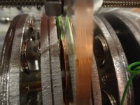
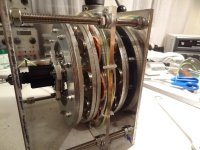
Building a triple stator axial flux motor

since i'm a bit ahead of my construction posts.... first trial run today with one stator ! about 1000 rpm, not properly aligned yet... driven by sine controller (of course :D )

[youtube]Fkzh1-qbBKw[/youtube]
 
Nice work !
 
Beautiful Lebowski! I love it! Such a great job putting that together and running it from your own also scratch-built controller that totally kicks ass. You are one of the very short list of elite folks in the world who can say they've made there own motor and sine controller to go with it, and we're proud to have you as a member my friend. :)
 
That's awesome. Looks like it is very well balanced. Good work, Lebowski. 8)
 
before I continue with the motor build, a simple test to see if the back iron is thick enough.
DSC01175.jpg

v1 was build with only one stator, each coil saw approximately 2 magnets, one on each rotor plate. Here we have 3 rotor plates with
a stack of 6 magnets distributed over 4 rotor plates. I don't really know what the effect of this change is on the (stator) perceived
magnetic field strength. So, before I continue making the 2 other stator plates I will put the motor together and see what the rpm/V
is for the middle and side stator plates. This will then tell me whether the magnetic field strength is the same for all stator plates, and
whether I'll get 1000 rpm at around 80V.

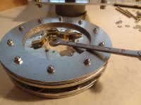
The magnet plates in the motor attract each other like crazy, count on forces around 100kg equivalent. To keep the rotor plates at an exact
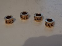
distance away from each other spacers are necessary. In my case I want 11mm spacers for a 7mm air gap (I have a 5mm thick stator).
The spacers will need to be longer than 11mm, the huge internal force will warp the end magnetic plates into bowl shapes. v1 for instance,
with the 14 magnets per plate and 4mm thick aluminium plates had a warpage of about 3mm. So the spacers there had to be 3mm longer than
necessary because the 4mm alu plate bends by about 1.5mm (on each side). I experimentally determined the warpage for v2 at 0.4mm

For a simple 1 stator motor, instead of making spacers like I do here you can also use a whole stack of standard little rings (cannot think of
the correct term now, the rings you put under each nut). In the case of my tripple stator, because of the small space for the motor in the
bike the motor is build very compact, I cannot use the rings because the outside diameter is too large. I will make spacers out of 10mm
brass tube (inside diameter 6mm).

DSC01198.jpg
DSC01196.jpg
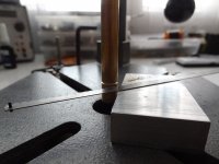
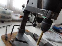
To set the drill height, I first fix the brass rod in the drill. The clamp blocking the drill is set very light so I can still move the drill down. The
spacer length is determine by the difference between the thickness of the alu block used to support the saw and whatever piece of aluminium
I place under the brass rod (in the picture above, the 3mm thick L-piece). Then press the drill down till the brass rod touches, tighten the
clamping block on the drill press and you're set to go.
DSC01195.jpg

DSC01201.jpg
 
Lebowski said:
before I continue with the motor build, a simple test to see if the back iron is thick enough.
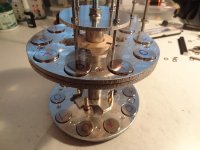
And did it stick lightly or strongly? :)

Geeked, KF
 
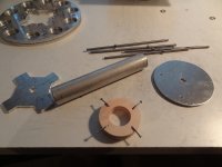
With the forces inside the motor, some sort of puller is necessary for assembly and disassembly.
DSC01191.jpg
The puller is made from a few pieces of aluminium, a tube, bolts and a wooden spacer. The thin bolts fit through the
4mm holes drilled in each rotor plate. The cross shaped alu plate allows insertion into the space where normally the
axle is located. Once inserted, rotate the puller so that it sits between the two plates to be pulled apart. There is
enough room to attach small bolts to the 4mm pulling rods.
DSC01192.jpg
DSC01193.jpg
The puller is necessary for both assembly and disassembly.
 
carefully assemble the rotor pack, make sure not to pinch the coil plate !
DSC01199.jpg
Insert the axle into the rotor pack after it's been assembled, if all your measurements are correct it should fit without problem.

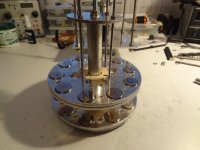
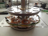
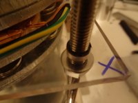
At the moment I have only 1 stator plate, so no spacers or anything are necessary there. The 'cage' of the motor is build using
8mm threaded rods. These go through the 10mm holes in the corners of the stator plates
DSC01203.jpg
View attachment 2
DSC01207.jpg
DSC01206.jpg
 
Lebowski said:
funnely enough the magnets are strongh enough to attract stainless steel, a material I always though to be non-magnetic...
Martensitic stainless steel is magnetic. Even Austentitic stainless steel is, very slightly.
 
subscribed -

Lebowski - I didn't find comment in this thread . . . can you muse on your motivation for a "coreless" approach on the stator ? Seems it would have been almost as easy to wind your coils around a steel hub, instead of acrylic . . . though this gives you no "back iron" per se, it should increase the field intensity inside the coil. Your 10/9 configuration should keep cogging out of the question, but I would presume your Kt could increase notably. (this would also lower Kv, and allow fewer turns of fatter copper {or 3 strands, e.g., in your case} for your target performance.
 
roller said:
subscribed -

Lebowski - I didn't find comment in this thread . . . can you muse on your motivation for a "coreless" approach on the stator ? Seems it would have been almost as easy to wind your coils around a steel hub, instead of acrylic . . . though this gives you no "back iron" per se, it should increase the field intensity inside the coil. Your 10/9 configuration should keep cogging out of the question, but I would presume your Kt could increase notably. (this would also lower Kv, and allow fewer turns of fatter copper {or 3 strands, e.g., in your case} for your target performance.

+1
Wound around a steel bobbin, if you will.

Oh and you are a hero to me. :)
 
you could certainly do that, Miles. . . long flat strip wound on the screw before the copper . . . could use the existing winding jig. There you go, Lebowski, take it apart.

I'm inclined to think that laminations are and improvement, but not 'required'. Or, that the net gain of laminations compared to a steel biscuit is much smaller than the net gain of (any) steel compared to air (acrylic).

FWIW, I think the fab process of making rod will align the grain boundaries along the length (if pulled, not rolled) , which is the desired direction in this application. Cut off discs and you're all end-grain along your flux vector. "Can I get that in 2% silicon steel?"
 
I've thought about using an iron core. Keeping in the spirit of using ordinary and easely available materials, I would wind
a coil-core out of coated iron wire. Here they sell plastic coated 1mm thick iron wire for use in the garden (tying bean stalks
etc). When wound this would give an iron core with (very) little eddy current losses. Reasons why I haven't done this, I think
it would make the motor impossible to assemble. The coil plate would bend a bit and the iron core would either attach
to the left or right magnet plate, it would be impossible to position the plate in the middle and not have it stick to either
magnet plate. Plus the forces on the magnet plates during assembly would be very difficult to handle.

Using solid disks as the core is a big no-no. The effect would be the same as shorting out the coils which locks the motor up solid.
 
Iron = losses

Ironless done right with good geometry to capture the generated flux naturally is the ultimate if you can achieve it.
 
Iron = torque density

torque density --> power density --> performance efficiency --> material efficiency = lower cost, higher performance . . . Thanks Steel!

What you lack in steel, you have to make up for in magnet and copper. I'd rather pay for steel.

70% or so of a motor's losses are in the copper, not the steel (depending on yaddah, yaddah . . ). Most of my work in designing a magnetic structure is balancing the losses -- bringing down the copper loss and putting it in the steel (reduce tooth width, add more copper, etc)

In Lebowski's case, (ignoring the legitimate flex issue), a stack of steel washers replacing the acrylic spud (though "laminated" in the wrong direction) would increase his T/A by maybe 3-4x (and maintain the home-build ethos). That makes life easy on a controller. He'll also drop his coil resistance by 50% or more when his torquier motor can now take fewer turns of fatter copper for the target speed.

Along those lines -- Lebowski -- what does this acrylic spud diameter do for you? Seems you could get more copper in by winding on a smaller diameter hub (of whatever mat'l). While not as easy - you might also consider (for the future) a trapezoidal or rectangular spud, so more of the winding path is running radially. The most useful forces will come from the tangent flux vectors, which are perpendicular to radial conductors.
 
I've read that you want your windings to match the shape of your magnets. I've also read stuff about windings smaller than the magnet not linking all the flux from the magnets or something like that. Often a couple windings smaller than the magnet will be okay because the smaller radius has less resistance, but too much and power benefits become negligible. Most of this is from the otherpower forum where people are building large coreless axial flux generators for their wind turbines.

And steel is very nice, except that it makes construction 10x harder because you will have extreme forces between the magnets and the stator. Extremely stiff rotor plates/stator along with very carefully placed thrust bearings to take up the axial force will be necessary. It's also difficult to get quality steel laminated in the right direction. I've read stuff about using powdered iron cores and machining them to shape, but that's not quite a homemade motor on the level of the one lebowski has built. Do some reading on the lrk-torquemax yahoo forum. Search "herbertkabi" and look at some of his posts. One can also see some hard data from tests of different wire types for a coreless motor.

http://groups.yahoo.com/group/lrk-torquemax/message/8211
 
roller said:
While not as easy - you might also consider (for the future) a trapezoidal or rectangular spud, so more of the winding path is running radially. The most useful forces will come from the tangent flux vectors, which are perpendicular to radial conductors.

I have thought about this, cause like you say, torque comes from the radial conductors (electrons running radially). This is when you think
of the whole construction as a motor and you think of torque coming from Lorentz forces.

I however consider the electromechanical machine I'm building as a generator, one in which I feed electrical power instead of extracting
electrical power. Keeping this in mind, for a good generator what you want is (for a fixed rpm and a fixed amount of windings) as high a voltage
as possible. This because then for a certain amount of power the current is lower and causes less losses.

So we need a structure which captures as much flux as possible (large area) but with a low resistance (short wiring length -> short circumvence
for the area). A circle is better with this respect than a rectangular shape.

The disadvantage of a circle however is that it takes up a lot of space. Around a certain motor circumvence you can only put so many
circles. This is actually how I came up with 9 coils for this motor, 9 coils of 4 cm is the most that will fit in the amount of space I have for
the motor in the bike. More coils means more magnets, meaning more erpm per rpm, meaning more voltage as the rate of flux change
is higher.

I'm starting to contradict myself here :cry: which typically means there's an optimum.

If you squeeze the circles a bit into ovals you can fit more in the circumvence (maybe 12 instead of 9), increase the amount of magnets
(go to 14 up from 10) and get more voltage.

Somewhere in the middle between a circle and a completely flattened oval there must be an optimum, must be calculatable....

But oval shape will definately be much more difficult to build.. Maybe it's time I look for a cheap laser cutting service...?
 
Back
Top