Building a triple stator axial flux motor

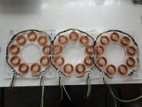
Regarding power numbers, I've only run it with one middle plate so it's preliminary but, I ran it at 5000 erpm (1000 rpm). This cost about
19 W of power. The voltage amplitude was 13V, current amplitude a bit less than 1 Amp. Inductance for 1 plate, 60 uH for 3 coils in series
as reported by my controller. Winding resistance should be 0.13 Ohm for 3 coils.

If the other plates are the same (same field strength), It'll need an amplitude of 40V for 1000 rpm (needing 80V battery) and have a resistance of 0.4 Ohm
per coil. 1 kW power in at 1000 rpm will then give 166 W in electrical losses and 834 W mechanical output (to be spend on mechanical losses
and propulsion). 1kW at 2000 rpm would give 42W electrical losses and 958W to be spend on the mechanical load (160V battery !).

I've run it up to around 1500 rpm at the moment, I got scared cause it was really moving ! A blown FET would have locked up the motor and
(cause of the rotor energy) thrown the thing across the room ! So I backed off... maybe I should screw it to the table.

Keep in mind, since I have a sine controller and use amplitudes instead of RMS, power = 1.5 * V_amplitude * I_amplitude , resistive power loss = 1.5 * I_amplitude^2 * R
 
moving the plate to one of the side slots gives the same results, there's less than 3% difference w.r.t. the plate in the middle.
So power and performance estimations from the previous post should be correct. It will spin at 2000 rpm but, I mean, then it
will pull 400 links of chain a second :!: so i think i'll limit myself to 1000 rpm

for some reason though the magnetic field is about 1.5 times as strong as in V1 .... :?: :? would be nice to have a magnetic field simulator...

I tried to get a paperclip to stick to the back iron but no luck, it might as well be a paperclip made from plastic.
Maybe this is the difference with V1, there it will stick but not very strong...
 
lebowski,
In your part of the world, try Senis. They are the cats meow of magnetic flux density probes/instruments. I am trying to get one located here in the USA to use in some experiments. I cannot find any University that has one.
kenkad
 
I'm not really interested in a measurement device to measure the stength of the magnetic field. I don't want
to know the absolute value, I want to know what the effects on the magnetic field are of geometrical changes to the motor....
 
Are you going to hook up your stators in parallel or in series? :)

~KF
 
1100 rpm :D one of the stator holes is cut a bit too tight, causing the ticking noise your hear. I think it will go away over time as the stator is shaved to size...

1100 rpm takes (0.42*64 = ) 27 W

[youtube]t9DsZRzuY3M[/youtube]
 
Nice and smooth. Great to see it running. Good job, Lebowski. 8) 8)
 
bravo sir.
hats off to you.
well done.
(you get the idea) :p
 
Really, REALLY, KEWL!!!

now just so I can be an unappreciative bastard.. How soon before you test it on a bike? The suspense is killing me.

but really that is an impressive display of what can be built with skilled hands and a few simple tools. excellent craftsmanship.

rick
 
Impressive work! :wink:

For more power do you plan on using backelite or FR4 instead of plexiglass?

Unless the use for this motor is demonstration and not use it for power?

Doc
 
No, this motor is fine as it is. The acryllic glass can take a very high temperature... I dropped solder blobs on it and
had a naked flame touching it for a short time (for the wire shrink stuff) but that did not affect it at all. The
magnet wire insulation will burn out before the acryllic glass gets hot enough to melt.

At 1000rpm it should deliver around 2000W mechanical output power so no, it is most definately not
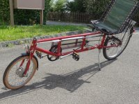
a demonstrator. It will go as a mid-drive in my recumbent. It was made to fit inbetween the horizontal
frame tubes of this bike:

DSC00787.jpg
 
I was wondering.... adding an iron core to the coils of my motor basically increases the magnetic
field through the center of the coils. Disadvantage of this approach is the eddy currents you get
in this iron as the magnetic field changes over time.

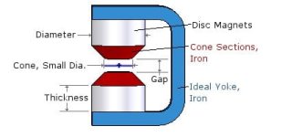
Another method would be to place small cones on the magnets, to concentrate the field more
in the center of the coils.... This would ( :?: ) have a similar effect as the approach of the previous
alinea, but without the eddy current losses.

Screenshot-8.jpg
 
Might be worth trying a simulation, first?

You'll get some eddy current losses in the copper, anyway. What's new is the hysteresis losses with the iron cores.
 
Miles said:
Might be worth trying a simulation, first?

You'll get some eddy current losses in the copper, anyway. What's new is the hysteresis losses with the iron cores.

Yeah but if you use cones on the magnets instead of cores in the inductors... I mean the
field inside the cones remains constant as it's the field coming from the magnets. The field
from the iron-less inductors, I don't know how strong it is but I don't think it's that strong. I've
always had the idea the motor runs on Lorentz forces, not on magnetic attraction.
 
Using FEMM, I found no advantage to lensing (+ it co$t more). For AF, the best advantage using any iron is as back iron terminating the end-plates, otherwise RF performs better: The horseshoe arrangement will not be practical in a multi-stator configuration, + it adds excessive mass. :|

BTW - I am excited to see this motor utilized on your recumbent: Very good work! 8)
Cheers! KF
 
did some more measurements... for different PWM frequencies

15 kHz -> (0.57 - 0.07) * 64 = 32 W
21 kHz -> (0.500 - 0.08) * 64 = 27 W
26 kHz -> (0.46 - 0.10) * 64 = 23 W

[pwm freq -> (current for motor at 1100 rpm - current at motor standstill) * supply voltage = watts into motor

So, interesting to see that a higher PWM freq takes less current to run the motor but costs slightly more controller current (probably in the gate driver circuits)
the motor was run with only 1 out of 3 plates used, the controller reports the motor inductance at 73 uH. For 1100rpm it makes a sine wave
centered around 50% dutycycle with an amplitude of 22% dutycycle....

it also shows the motor only needs 23W for 1100 rpm... very very low value I would say (remember that 1100 rpm, for the Deore axle used, is like
riding your bike at 135 kmh)
 
Back
Top