Quick disconnect for phase wires

amberwolf said:
Note that if you don't preheat the wire to soldering temperatures before inserting it into the molten solder, you instantly create a cold-solder joint, which is fractured at the interface and doesn't penetrate / wick into the strands of the conductor. :( It may "stick" to surfaces enough to not separate when pulled, but it is nowhere near as good a bond as if everything were at the same, correct, temperature for long enough to allow good solder flow over all surfaces.

Thank you, Very helpful to know! Will preheat the wire this time :wink:
 
Also...I found that using a flame directly on any copper can oxidize it and make it not stick as well to the solder/etc, if the copper gets too hot. Or it makes the flux in the solder burn off so fast it can't do the cleaning job it's meant to, so if the copper or other surface was already oxidized it might not bond the same way to the solder either.

Not usually a problem, but something to keep an eye out for, that doesn't typically happen when using a heated (electrically or chemically) metal soldering tip instead of an open flame.
 
Well no turning back now :shock: :lol:
That’s actually my old motor QS205 V3 but will re-lace with a 16 inch rim with a street tire. The newer motor V3TI has a Enduro tire with a 16 inch rim. It will be nice to be able to switch between motors due to the quick connect/disconnect. You can see in the picture I’ve connected the hall sensor waterproof connector going to the controller. Had to buy two of those connectors since I have two motors. I really only needed 1 1/2 :lol:

I was going to post this on my Enduro build thread but figured I would update this as well. Maybe this will help generate some ideas for someone else out there looking for a quick connect/disconnect. Sometimes us just seeing images can help us think of new ideas so we should all document our custom builds :thumb:

Probably will make a little plastic Cover for the connectors to protect from impact from Enduro riding. Probably could use some Velcro so it’s easily removable to swap motors. Something along those lines :wink:
 

Attachments

  • DFCA2FFA-E127-490E-931B-9EF066A2E86C.jpeg
    DFCA2FFA-E127-490E-931B-9EF066A2E86C.jpeg
    3.6 MB · Views: 504
  • 852380FB-EC7E-41E5-85B2-B3E91CD51B7D.jpeg
    852380FB-EC7E-41E5-85B2-B3E91CD51B7D.jpeg
    2.7 MB · Views: 504
  • BB56C73C-17E4-471B-A32E-52A2F642063E.jpeg
    BB56C73C-17E4-471B-A32E-52A2F642063E.jpeg
    3.3 MB · Views: 504
Technical question.
So most of you know the QS205 has two sets of hall sensors.
So I’m trying to figure out which wire is my speed sensor.
So both sets of hall sensor wires contain a clear wire. One of the wires is for the hall sensor and the other wire is for the speed sensor. They colorcode each set differently but each set contains that clear wire and I can’t figure out which one I need to connect. I tested the voltage and they both show -3.1 and I don’t want to connect either one and short something out if that’s even possible. How can I figure out which is the speed sensor wire? Hopefully this makes sense it’s kind of hard to explain it lol
So both sets of hall sensor wires contain a clear wire but the wire does not serve the same purpose for each set, one is a speed sensor and the other one is a actual hall sensor wire :confused:

I can connect one it and spin the wheel with the throttle and look on the app to see the RPMs moves but I’m just worried if I connect that hall sensor to the speed sensor wire it could short something in the controller, Beyond my knowledge.
 

Attachments

  • 6EB855C8-D9E3-47B1-BCA2-643051E151CE.jpeg
    6EB855C8-D9E3-47B1-BCA2-643051E151CE.jpeg
    103 KB · Views: 474
  • 931718A8-16BE-48B4-9983-377E04AD191C.jpeg
    931718A8-16BE-48B4-9983-377E04AD191C.jpeg
    283.8 KB · Views: 472
Are you sure your QS205 has a separate speed sensor?

The QS205s (dunno which version or winding, but I think they're both the 50H stators) I have do not have separate speed sensors, but they do have temperature sensors.

Anything I were to hook up to them that read speed would be doing it using one of the regular hall sensors.

Regarding a speed sensor vs a hall sensor: A speed sensor (all the ones I've ever seen) uses separate magnets on the side cover, rather than the rotor magnets. So it will have a different pole count and thus different number of pulses per rotation (lots fewer) than the hall sensors. That should make it easy to tell the difference between a speed sensor wire and a hall sensor wire; just manually rotate the motor, with the hall signals connected to a powered up controller. Measure from ground to each hall signal, and count the pulses as you turn the wheel. You should get a couple dozenish for each hall signal, per wheel rotation. A speed sensor, when connected to one of the controller hall wires, will have a lot less pulses than that (actual number will depend on how many magnets are in the cover near the sensor, or wherever the sensor is placed).


I don't know if this is the case on your cabling, but most of the time a "clear" covered "gray" (silver) wire is a shield-ground wire, connecting to a braided or foil shield around a bunch of signal wires to keep electrical noise out of them. The shield is usually only connected at one end (so in this case, at the controller ground, not the motor hall ground). If this is how yours is wired, there will be no continuity for the clear/gray wires to any other wire in the cable, or any connection inside the motor (only to the shield around the wires, if there is one).

If your clear/gray wires are not shield ground wires, and are actually signal wires, and do not have hall signals on them, then they are probably for a thermistor signal.

I don't think my QS205s have dual thermistors to go with the dual halls--they only have one thermistor, whcih is wired to teh same ground as the halls, and then has it's own signal wire. I don't know what color the wires are, but I can take a look, since both stators are not inside covers ATM (only one even has a rotor or covers; the other is just a stator). IIRC one of the wire sets only has 5 wires (3 hall signals, power, and ground), and the other has 6 (because it has the thermistor too).
 
amberwolf said:
Are you sure your QS205 has a separate speed sensor?

You’re probably right, it could be the temp sensor wire. It’s one of the two because all the other wires are accounted for so either temp or speed sensor.

amberwolf said:
Just manually rotate the motor, with the hall signals connected to a powered up controller. Measure from ground to each hall signal, and count the pulses as you turn the wheel. You should get a couple dozenish for each hall signal, per wheel rotation. A speed sensor, when connected to one of the controller hall wires, will have a lot less pulses than that (actual number will depend on how many magnets are in the cover near the sensor, or wherever the sensor is placed).

OK I’ll do this test to figure out what this mysterious wire is. At the end of the day I know it’s just optional, as I don’t have a display for speed or a temp display, although my controller does have a temperature setting to limit current while overheating but have it turned off, I don’t normally get the hub that hot.

I really appreciate your input Amberwolf! You’re a treasure too ES :thumb:
 
Maybe the following threads will help:

https://electricbike.com/forum/forum/main-forum/general-discussions/49474-qs-motor-temp-sensor-and-spare-hall-effect-sensor-wiring

https://electricbike.com/forum/forum/main-forum/general-discussions/50400-how-to-connect-qs-motor-temp-sensor-to-cycle-analyst-v3
 
Eastwood said:
OK I’ll do this test to figure out what this mysterious wire is. At the end of the day I know it’s just optional, as I don’t have a display for speed or a temp display, although my controller does have a temperature setting to limit current while overheating but have it turned off, I don’t normally get the hub that hot.

If the temp sensor is using a common ground with the hall sensors, then you can measure the resistance between the mystery wire and ground to get an idea what type you have (10k ohm is common). If you put the motor in the sun or a cooler spot, the reading will change.
 
gobi said:
Maybe the following threads will help:

https://electricbike.com/forum/forum/main-forum/general-discussions/49474-qs-motor-temp-sensor-and-spare-hall-effect-sensor-wiring

https://electricbike.com/forum/forum/main-forum/general-discussions/50400-how-to-connect-qs-motor-temp-sensor-to-cycle-analyst-v3

Thank you, very useful!
:thumb:


E-HP said:
If the temp sensor is using a common ground with the hall sensors, then you can measure the resistance between the mystery wire and ground to get an idea what type you have (10k ohm is common). If you put the motor in the sun or a cooler spot, the reading will change.

OK great, I’ll test the Sensor :thumb:

And I just thought of this, I should’ve just hooked up a thermostat to one of the wires and see which one gives me an actual temperature reading right? lol seems like a pretty simple approach but I’m just now thinking of this after reading all of you guys input.
Have quite a few little thermostats that I’ve used on previous ebikes. Or maybe I should just install one so I can keep an eye on those temperatures in this hot summer coming up.

Thanks guys!!!

I’ll still check the Ohm reading as well.
 

Attachments

  • 533C0856-92E1-4984-9DE8-6FD936E18036.jpeg
    533C0856-92E1-4984-9DE8-6FD936E18036.jpeg
    4 MB · Views: 383
  • 84D58182-3706-4601-9447-C5BBE2E56B4B.jpeg
    84D58182-3706-4601-9447-C5BBE2E56B4B.jpeg
    2.9 MB · Views: 383
  • BE1CE5B6-85F9-4201-B5D9-686B9972DD45.jpeg
    BE1CE5B6-85F9-4201-B5D9-686B9972DD45.jpeg
    2.1 MB · Views: 383
E-HP said:
Eastwood said:
OK I’ll do this test to figure out what this mysterious wire is. At the end of the day I know it’s just optional, as I don’t have a display for speed or a temp display, although my controller does have a temperature setting to limit current while overheating but have it turned off, I don’t normally get the hub that hot.

If the temp sensor is using a common ground with the hall sensors, then you can measure the resistance between the mystery wire and ground to get an idea what type you have (10k ohm is common). If you put the motor in the sun or a cooler spot, the reading will change.

Both wires measured at 1 ohm :shock:
So I guess they’re both 1 ohm thermal resistors?

Come to think of it, I always remember the controller display showing 0°C For the motor temp “maybe” because the resistor isn’t compatible with sabvoton controller.
 
Eastwood said:
Both wires measured at 1 ohm :shock:

Your multi meter can measure 1 ohm accurately?

Wow. My 799$ multimeter cannot. Its got about 20,000 pixels for a screen but it cannot measure a single ohm.. nope nosiree. Its bottom line is about 20 ohm..... nor can my 599$ one.. 999.9 Ω ± (1.0% + 5 digit) ..AKA .. ( 10 ohms +/- resolution). Nor any of the cheaper ones.
 
DogDipstick said:
Eastwood said:
Both wires measured at 1 ohm :shock:

Your multi meter can measure 1 ohm accurately?

Wow. My 799$ multimeter cannot. Its got about 20,000 pixels for a screen but it cannot measure a single ohm.. nope nosiree. Its bottom line is about 20 ohm..... nor can my 599$ one. Nor any of the cheaper ones.

Well mine is cheap, so maybe the reading is wrong. It measures at 1.1 ohm
 
Eastwood said:
Well mine is cheap, so maybe the reading is wrong. It measures at 1.1 ohm

Well what is the model and I'll tell you the spec. My expensive meter considers anything under 20 ohms a "short" and goes to O.L. (over load range) ( open loop) (watever teh " Ol" means) ,.
 
Eastwood said:
Both wires measured at 1 ohm :shock:
So I guess they’re both 1 ohm thermal resistors?
1ohm is probably the resistance of the meter leads plus that of the wires being measured, but with most meters it isn't really accurate to that degree. The manual for the meter usually lists it's accuracy and error "rate", or percentage it may be "off" from what you actually see on the screen.


FWIW, you'd get around that reading or less if those wires are shield-ground wires that are tied to the main ground wire. (assuming you're measuring in the lowest ohm range of the meter, typically 20ohm or 200ohm, and putting the black lead on the signal ground wire of the signals connector and the red lead on the wire under test. )
 
DogDipstick said:
Your multi meter can measure 1 ohm accurately?
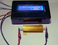
Exactly what I was thinking. I have a special meter for reading low resistances.

It is a HR-390 that I got via a slow boat via FleaBay.
As far as I know it is the least expensive thing that can accurately read resistance under about 10 Ohms.
I have tested it and it appears to be within about 5 milliohms.

(it reads from zero to 120 ohms but I have not tested the top end)
Mini Ohm Meter(600).jpg

*** now someone is going to ask "how did you test it" ?
I ran a known current (from my Riden RD6006 Power Supply) through some low resistance precision resistors and measured the voltage drop with a pair of 4000 count DDMs. Then I calculated the actual resistance and compared it to what the HR-390 gave me. Hint ... when one gets down into the milliohm range you need a lot of current (I used 5 amps).
 
Well did a 10mile test and the connectors held up well with 450 phase amps. 8)
Figured I would report back and give the results. Thanks for the suggestion guys for the 8 mm bullets, like these connectors. I should’ve used these for my battery connections compared to the XT 90, definitely beefier. Stopped a few times after hammering the throttle at 450 phase and the wires and connectors still felt cool.

I still need to tidy up everything and heat shrink. Wanted to give it a good test before I made 100% complete.

Thanks again guys for all the input!
Hopefully this thread could be useful for someone else out there :thumb:
 

Attachments

  • FA705038-1DF3-41B4-9910-1BAE7B448F37.jpeg
    FA705038-1DF3-41B4-9910-1BAE7B448F37.jpeg
    2.5 MB · Views: 293
Back
Top