battman
1 W
Hi Folks,
This thread describes a circuit to take the signal voltage from a 5V throttle and remap that voltage under software control of a Picaxe chip.
I have an electric bicycle with a Grin Technologies Phaserunner V2 with a single throttle providing both drive and regen braking. With this configuration, the software for the controller only allows a region of regen, then freewheel/ neutral, then drive.
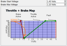
I wanted a second region of freewheel on a fully closed throttle. This would allow me to do things such as hop off the bike and push it through a gate without having to either finesse the throttle to create a voltage in the standard neutral region, or switch the controller off. Or to coast down a hill no-hands without switching the controller off. The picture below clarifies the goal a little;
Not everyone's use cases for sure, but given the Picaxe, you can program it to remap the throttle any way you see fit. The Picaxe ADC, using 8 bit resolution, is sufficient for the throttle signal input. But the Picaxe DAC is insufficient for output to the controller for the following reasons;
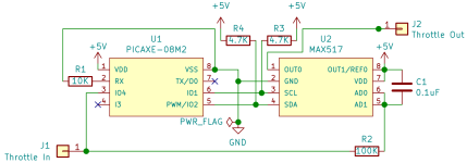
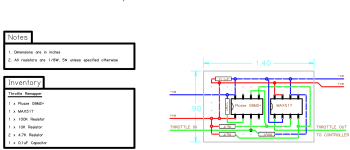
To address these issues, a MAX517 8-bit DAC is incorporated. The full circuit and perfboard layout are below;
And the end result looks like this;
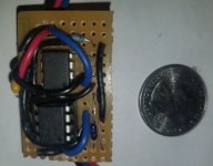
The picaxe chip is in a socket so that it can be pulled and the code tweaked on an external breadboard programming circuit I was using. Alternatively, the socket could be eliminated and a couple more resistors and 3.5mm jack could be tossed onto the perfboard to allowing reprogramming there.
The Picaxe code for adding the second freewheel region is below. It just remaps a throttle signal of 0.9V or less (closed throttle) into the neutral region of the Phaserunner map.
I encountered two issues during testing that may be worth recounting should anyone else embark on a similar project and notice the same behaviors;
That's pretty much it. Hope someone else can get some use from this circuit too, or find some problems and improvements in it and help with my ever ongoing electrical education!
This thread describes a circuit to take the signal voltage from a 5V throttle and remap that voltage under software control of a Picaxe chip.
I have an electric bicycle with a Grin Technologies Phaserunner V2 with a single throttle providing both drive and regen braking. With this configuration, the software for the controller only allows a region of regen, then freewheel/ neutral, then drive.
I wanted a second region of freewheel on a fully closed throttle. This would allow me to do things such as hop off the bike and push it through a gate without having to either finesse the throttle to create a voltage in the standard neutral region, or switch the controller off. Or to coast down a hill no-hands without switching the controller off. The picture below clarifies the goal a little;

Not everyone's use cases for sure, but given the Picaxe, you can program it to remap the throttle any way you see fit. The Picaxe ADC, using 8 bit resolution, is sufficient for the throttle signal input. But the Picaxe DAC is insufficient for output to the controller for the following reasons;
- The DAC only has a 5 bit/ 32 voltage level resolution.
- Very limited current sourcing capability.
- Inability to generate full 0-5V range.
To address these issues, a MAX517 8-bit DAC is incorporated. The full circuit and perfboard layout are below;


And the end result looks like this;

The picaxe chip is in a socket so that it can be pulled and the code tweaked on an external breadboard programming circuit I was using. Alternatively, the socket could be eliminated and a couple more resistors and 3.5mm jack could be tossed onto the perfboard to allowing reprogramming there.
The Picaxe code for adding the second freewheel region is below. It just remaps a throttle signal of 0.9V or less (closed throttle) into the neutral region of the Phaserunner map.
Code:
; MAX517 DAC with address bits AD0=AD1=0
#define DAC_I2C_ADDRESS 		%01011000
#define DAC_SET_VOLTAGE_CMD		%00000000
#define DAC_RESET_CMD      		%00010000

; Use power supply -ve and +ve for ADC voltage reference
#define ADC_CONFIG			%000
; Voltage below which throttle is considered to be in minimal mechanical position. Set to 0.9V
#define IDLE_THROTTLE_THRESHOLD	46
; Neutral throttle voltage, between acceleration and braking. Set to 1.45V
#define NEUTRAL_THROTTLE		74

#define THROTTLE_PIN			C.4
#define THROTTLE_VALUE 			B0

	adcconfig ADC_CONFIG
	hi2csetup i2cmaster, DAC_I2C_ADDRESS, i2cslow, i2cbyte

	hi2cout (DAC_RESET_CMD)

read_throttle:
	readadc THROTTLE_PIN, THROTTLE_VALUE
	if THROTTLE_VALUE < IDLE_THROTTLE_THRESHOLD then
		; Remap closed throttle to neutral position
		THROTTLE_VALUE = NEUTRAL_THROTTLE
	endif
	hi2cout (DAC_SET_VOLTAGE_CMD, THROTTLE_VALUE)

	goto read_throttle
I encountered two issues during testing that may be worth recounting should anyone else embark on a similar project and notice the same behaviors;
- I had initially "cheaped out" and not included C1, the 0.1uF capacitor. This caused some inconsistent and choppy throttle behavior.
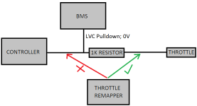
- I am using a BMS that pulls the throttle signal to 0V on LVC. A 1K resistor is used to prevent a short circuit between the throttle signal and the 0V pulldown. I had initially installed the remapper on the controller side of that pulldown circuit. This resulted in the 1K resistor preventing the Picaxe ADC from reading voltage correctly with the exciting result that on letting go of full throttle ... the bike kept accelerating! So, per the diagram below, the remapper must be installed on the throttle side of the pulldown circuit.

That's pretty much it. Hope someone else can get some use from this circuit too, or find some problems and improvements in it and help with my ever ongoing electrical education!

