New "TSDZ2 Torque Sensor Central Motor"

I know this has been discussed a million times here, but i need to be sure before buying a battery pack for my OSF flashed 36v TSDZ2b motor.

Background:
I'm converting my vintage 24" bmx bike into an e-bike and i bought and installed the 36v TSDZ2b motor version, because the only battery pack (at that time which i found on ali) which would fit (small enough) the bmx frame was an 36v/20ah battery pack (no-brand 18650 batteries).

BUT, i now found a 48v/25ah pack (samsung 18650's) which is a little bit bigger but would also fit inside the frame (more expensive, but that's ok for me).

I read here that a 48v battery on a 36v motor would keep the motor cooler at the same wattage as a 36v battery on a 36v motor. Is this true?

Will a 48v battery on a 36v motor also make the bike more snappier/responsive (i also want to use a thumb throttle in case i get too tired pedaling ;)?

What would be the advantages/disadvantages using a 48v battery over a 36v battery with a 36v motor?
Or does it really not matter and just buy the cheapest (36v battery pack)?

Should i go for the 48v battery pack or get the 36v battery pack?

BTW: I already have flashed the OSF.

BR,
Ray
 
I'm wondering if anyone has taken steps to machine down the width of the Bottom Bracket shell on the drive side of their frame, in an effort to move the TSDZ2 closer to the centerline of the bike?

I'm putting a TSDZ2 on a kids MTB, and while I can get the Q-factor down to around 186mm with the correct cranks, the motor is still offset around 15mm to the drive side.

I could easily machine about 7-8mm off the drive side bottom bracket shell before I hit any welds or encounter any chainstay clearance issues etc. This would almost perfectly center the cranks and retain the narrow Q-factor.

Obviously this would be an irreversible change to the frame and it would unlikely be usable as a normal bike again, but we're talking a $50 secondhand 24" MTB frame so I'm not too concerned about that.

Just interested to see if others have gone to such lengths?
 
Major Clod said:
I'm wondering if anyone has taken steps to machine down the width of the Bottom Bracket shell on the drive side of their frame, in an effort to move the TSDZ2 closer to the centerline of the bike?

I'm putting a TSDZ2 on a kids MTB, and while I can get the Q-factor down to around 186mm with the correct cranks, the motor is still offset around 15mm to the drive side.

I could easily machine about 7-8mm off the drive side bottom bracket shell before I hit any welds or encounter any chainstay clearance issues etc. This would almost perfectly center the cranks and retain the narrow Q-factor.

Obviously this would be an irreversible change to the frame and it would unlikely be usable as a normal bike again, but we're talking a $50 secondhand 24" MTB frame so I'm not too concerned about that.

Just interested to see if others have gone to such lengths?

Yup I did exactly this, took about 5mm off the drive side to get chainline better. Seemed to work pretty good as chainline is decent even with my 30T chainring and I do use the lowest gear a lot. I did it mostly for chaining but did improve Q-factor as I also have the the straight crank on that side as well. I actually just used an angle grinder with a waxed sanding wheel and ground down and checking for an even cut with calipers.
 
alright so the TSDZ2 B version is out for a while (on pswpower at least) - has anyone gathered some experience with this drive? did they make heat dissipation any better? is the new gear stronger? they didnt happen to fix problems that the old version suffers from, did they?
 
Anyone that wants to run TSDZ2 with VESC to have the best performance possible, can do the same I am doing for my EBike that has a Bafang M500 motor.

VESC is the best motor controller and is generic, it can drive any motor and I already did run TSDZ2 with it - see this video.

For the EBike application, I am using ESP32 board that runs simple Python firmware and controls the motor sending commands to VESC. I can develop/program wirelessly the EBike board, using my phone (like when I am outside riding!!) as also I can receive in real time motor and EBike application data. See the results of my early tests:

-------------------------------------

This were quick early tests, but here a video of me pushing the pedals with my hand, and the motor reaction to it: https://www.youtube.com/watch?v=Xki6n73GpXk

[youtube]Xki6n73GpXk[/youtube]

The piece of code that reads the torque sensor weight value in kgs and maps to the motor current:


NOTE: the code is missing the current ramp, to keep the current increase in control and slow, to avoid damage of the gears, etc. Still, I did some very short rides and it seems to work very well, It made me happy!! and as you can see, both motor start and stop, is not noisy, it is similar to original motor firmware, which is good!!

The firmware as also a task code to output some useful data, I get this in real time in my phone:
1. torque weight value in kgs
2. cadence
3. brake state
4. motor current (read from VESC)


My next step is to implement the motor current ramp. Then probably I will connect the display and start riding my EBike while I will be tweaking the firmware to have the motor response I am looking for. In begin of February I will have some MTB events, so by then I hope to have all the system ready, this means also everything water resistant!

Code and other information are on Github: https://github.com/OpenSourceEBike/EBike_EScooter_app_pyhton
 
I don't think that you need the current ramp in this application. The motor produces constant torque @ constant current. I believe the reason that the current ramps were beneficial the TSDZ2 project was because battery current and not phase current was controlled. Phase current (which determines the torque) can vary wildly with constant battery current.
 
Vbruun said:
I don't think that you need the current ramp in this application. The motor produces constant torque @ constant current. I believe the reason that the current ramps were beneficial the TSDZ2 project was because battery current and not phase current was controlled. Phase current (which determines the torque) can vary wildly with constant battery current.
Hmmm, I will implement it anyway, should be easy if I take as reference the VESC implementation. In the end, the parameters can be 0 and then the ramp will be disabled, if that makes sense.
 
casainho said:
Anyone that wants to run TSDZ2 with VESC to have the best performance possible, can do the same I am doing for my EBike that has a Bafang M500 motor.

VESC is the best motor controller and is generic, it can drive any motor and I already did run TSDZ2 with it

I got a couple of the mini flipskys recently - hooked one up to a bare tsdz2 motor today, works fine as you say. In your video are you running sensorless? - looks like you might have the hall sensor cable connected to the motor but the wires go offscreen so I can't tell. I've had it running fine sensorless so haven't bothered connecting the hall sensors.

I'm considering converting one of my bikes to vesc as a stepping stone to a different motor. I might use my existing nrf52840s and have them talk to the flipskys over UART. Would need to move the torque/pas sensors to the nrf too i assume - but think it should be relatively straightforward and a nice little project. That would mean moving the nrf inside the motor case most likely - but that's not a bad thing as long as bluetooth still works.
 
beemac said:
casainho said:
Anyone that wants to run TSDZ2 with VESC to have the best performance possible, can do the same I am doing for my EBike that has a Bafang M500 motor.

VESC is the best motor controller and is generic, it can drive any motor and I already did run TSDZ2 with it

I got a couple of the mini flipskys recently - hooked one up to a bare tsdz2 motor today, works fine as you say. In your video are you running sensorless? - looks like you might have the hall sensor cable connected to the motor but the wires go offscreen so I can't tell. I've had it running fine sensorless so haven't bothered connecting the hall sensors.

I'm considering converting one of my bikes to vesc as a stepping stone to a different motor. I might use my existing nrf52840s and have them talk to the flipskys over UART. Would need to move the torque/pas sensors to the nrf too i assume - but think it should be relatively straightforward and a nice little project. That would mean moving the nrf inside the motor case most likely - but that's not a bad thing as long as bluetooth still works.
I tested only sensorless. On Bafang M500 I am now testing sensorless and it gives bad results, so I am now trying to use as original board does, using a magnetic sensor. My advice for you is to use the hall sensors, you will have then for sure a very good motor startup.

Yes, you will need to be able to read the torque sensor and PAS. I am curious if you can replicate the original circuit of TSDZ2 motor controller!! Will you do it??

I would say any board to work wireless, can not be placed inside a metal box, like the TSDZ2 metal case.

Please share pictures and videos of your tests!!

And what would be the final motor you would use??
 
casainho said:
I tested only sensorless. On Bafang M500 I am now testing sensorless and it gives bad results, so I am now trying to use as original board does, using a magnetic sensor. My advice for you is to use the hall sensors, you will have then for sure a very good motor startup.

Yes, you will need to be able to read the torque sensor and PAS. I am curious if you can replicate the original circuit of TSDZ2 motor controller!! Will you do it??

I would say any board to work wireless, can not be placed inside a metal box, like the TSDZ2 metal case.

Please share pictures and videos of your tests!!

And what would be the final motor you would use??

Ok, i'll see if there's much difference if I connect the sensors.

My idea is to keep things as similar as possible to the existing wireless setup to allow reuse of the existing parts/code and minimise bike-rewiring if possible!

Replace the tsdz2 controller with a mini flipsky and an nrf which acts like a cycle analyst and takes all the inputs and provides a single throttle output - in this case over UART to the vesc - but in future would be easy to add canbus or traditional throttle output if needed for other projects.

I had hoped there was an external antenna connector on the nrf dongle - but seems not, so i'll either have to mount that outside or swap to a board with an antenna connector - but will have to be close to get the additional sensor wires to it.

i was in two minds about making the new controller a replacement for the tsdz2 controller only - and so keep the other nrf handling the ebikeapp and bluetooth but I think it's nicer to have everything running on a single nrf inside or close to the motor. I'd still have a cable running from the handlebar to the motor for brakes/buttons in my case since I didn't ever build the wireless remote.
 
beemac said:
Ok, i'll see if there's much difference if I connect the sensors.

beemac said:
I had hoped there was an external antenna connector on the nrf dongle - but seems not, so i'll either have to mount that outside or swap to a board with an antenna connector - but will have to be close to get the additional sensor wires to it.

I am using ESP32 now, because I can program it wireless but not on the NRF52840 -- CircuitPython wireless programming has some big issues for NRF52840. There is another advantage as the ESP32 runs much faster: 240MHz VS 64MHz, and that is important because Pyhton code is slow so having big processing power is nice.

BUT, there are ESP32 boards that has external antenna connector -- just look at Aliexpress.
 
casainho said:
beemac said:
Ok, i'll see if there's much difference if I connect the sensors.

beemac said:
I had hoped there was an external antenna connector on the nrf dongle - but seems not, so i'll either have to mount that outside or swap to a board with an antenna connector - but will have to be close to get the additional sensor wires to it.

I am using ESP32 now, because I can program it wireless but not on the NRF52840 -- CircuitPython wireless programming has some big issues for NRF52840. There is another advantage as the ESP32 runs much faster: 240MHz VS 64MHz, and that is important because Pyhton code is slow so having big processing power is nice.

BUT, there are ESP32 boards that has external antenna connector -- just look at Aliexpress.

thanks, yea I think for now I'll stick with the nrf as I have a few lying around and i'll cut-n-paste the existing code to get things working rather than shift to python and rewrite from scratch. I can't see that much of an advantage moving to python (although that's probably because I've not used it much) - and the idea of getting faster microcontrollers just to be able to use a less efficient language irks the old z80 programmer in me :lol:

Is it that much easier to write the ebike parts in python rather than c? I'd have though once you have the functions setup that deal with hardware and sensors and so on - the actual logic of the the ebike app would be pretty simple code in either c or python?
 
beemac said:
I can't see that much of an advantage moving to python (although that's probably because I've not used it much) - and the idea of getting faster microcontrollers just to be able to use a less efficient language irks the old z80 programmer in me :lol:

Is it that much easier to write the ebike parts in python rather than c? I'd have though once you have the functions setup that deal with hardware and sensors and so on - the actual logic of the the ebike app would be pretty simple code in either c or python?
Python is a fast developing learning and easy to learn. I am seeing Arduino shifting from C++ to Python.

For me, it is very important fast development!! Other all this advantages of Python (nice even for new developers, as anyone can develop Pyhton code), CircuitPython also let us develop/program/debug the code wireless with out phones -- because of this I am being testing the EBike application while riding and using my phone on my pocket, no need anymore to have a computer and connect a specific cable to development and debug, this is way faster!!

This is how I edit the code on my phone, wirelessly while the Ebike board is installed inside the EBike motor:


And here is the prints data on the terminal:


And I am also writing the debug data on a CSV file inside the board, so on the same file system the Pyhton code is being run, it can also write and read files!! this is magic, it seems almost a Linux system. Although, all this magic needs much more processing power / energy and yes, doing all this is kind of slow but works ok for my application:

 
casainho said:
beemac said:
I can't see that much of an advantage moving to python (although that's probably because I've not used it much) - and the idea of getting faster microcontrollers just to be able to use a less efficient language irks the old z80 programmer in me :lol:

Is it that much easier to write the ebike parts in python rather than c? I'd have though once you have the functions setup that deal with hardware and sensors and so on - the actual logic of the the ebike app would be pretty simple code in either c or python?
Python is a fast developing learning and easy to learn. I am seeing Arduino shifting from C++ to Python.

For me, it is very important fast development!! Other all this advantages of Python (nice even for new developers, as anyone can develop Pyhton code), CircuitPython also let us develop/program/debug the code wireless with out phones -- because of this I am being testing the EBike application while riding and using my phone on my pocket, no need anymore to have a computer and connect a specific cable to development and debug, this is way faster!!

And I am also writing the debug data on a CSV file inside the board, so on the same file system the Pyhton code is being run, it can also write and read files!! this is magic, it seems almost a Linux system. Although, all this magic needs much more processing power / energy and yes, doing all this is kind of slow but works ok for my application:

Ok, can see the benefit from the point of view of not needing to build/flash etc. makes life a lot simpler - and I know it's something that's useful to learn, i'm just not sure I have enough time to start from scratch with python.

Just building a new nrf dev board since I blew my last one up when I left my power supply in constant current mode by mistake, one check to add to the list - I'd checked the open circuit voltage of my psu first but didn't think to check it wasn't in cc mode...cue magic smoke :(

Hoping I have enough pins on the nrf for everything - buttons, pas, torque sensor, speed sensor etc. think I'd better work that out before I start soldering!
 
beemac said:
Hoping I have enough pins on the nrf for everything - buttons, pas, torque sensor, speed sensor etc. think I'd better work that out before I start soldering!

Can anyone help with how the torque sensor works from an electrical point of view and how i might interface it to the nrf? Reading the value with an adc pin is no problem - it's the 'exciting' part that I'm not sure if I need additional circuitry for...

"The torque sensor signal is measured on ADC channel 3. There is a specific circuit to excite the primary coil of the torque sensor and it needs a pulse signal that is generated on PD3 and has a period of 20us and a 2us Ton:" - taken from https://opensourceebikefirmware.bit...TSDZ2_mid_drive_motors--Motor_controller.html

It's the 'specific circuit' part that makes me think I can't just use a 5v pulse from the nrf to excite the torque sensor. If it's not a logic level device I presume I need to switch a mosfet/transistor to provide a bit more current to excite the torque sensor circuit?

I found this - but doesn't help unfortunately https://endless-sphere.com/forums/viewtopic.php?f=28&t=79788&start=9300#p1713302
 
beemac said:
beemac said:
Hoping I have enough pins on the nrf for everything - buttons, pas, torque sensor, speed sensor etc. think I'd better work that out before I start soldering!

Can anyone help with how the torque sensor works from an electrical point of view and how i might interface it to the nrf? Reading the value with an adc pin is no problem - it's the 'exciting' part that I'm not sure if I need additional circuitry for...

"The torque sensor signal is measured on ADC channel 3. There is a specific circuit to excite the primary coil of the torque sensor and it needs a pulse signal that is generated on PD3 and has a period of 20us and a 2us Ton:" - taken from https://opensourceebikefirmware.bit...TSDZ2_mid_drive_motors--Motor_controller.html

It's the 'specific circuit' part that makes me think I can't just use a 5v pulse from the nrf to excite the torque sensor. If it's not a logic level device I presume I need to switch a mosfet/transistor to provide a bit more current to excite the torque sensor circuit?
I wrote that text about the 2us pulse (50kHz 10% duty-cycle), etc. I did that by observation with oscilloscope and then I just replicated on our OpenSource firmware, and then it just worked at the first try.

I would say there is some "power" circuit to be able to drive the coil, starting from that input pulse of 50kHz 10% duty-cycle. I would look at the TSDZ2 motor controller to try figure out what can be the circuit, but probably just some mosfet to switch on/off that signal. And the reading back circuit, I have no idea, but as this motor controllers are kind of cheap, anyone can try to use a new one just to figure out the circuit.
 
casainho said:
beemac said:
beemac said:
Hoping I have enough pins on the nrf for everything - buttons, pas, torque sensor, speed sensor etc. think I'd better work that out before I start soldering!

Can anyone help with how the torque sensor works from an electrical point of view and how i might interface it to the nrf? Reading the value with an adc pin is no problem - it's the 'exciting' part that I'm not sure if I need additional circuitry for...

"The torque sensor signal is measured on ADC channel 3. There is a specific circuit to excite the primary coil of the torque sensor and it needs a pulse signal that is generated on PD3 and has a period of 20us and a 2us Ton:" - taken from https://opensourceebikefirmware.bit...TSDZ2_mid_drive_motors--Motor_controller.html

It's the 'specific circuit' part that makes me think I can't just use a 5v pulse from the nrf to excite the torque sensor. If it's not a logic level device I presume I need to switch a mosfet/transistor to provide a bit more current to excite the torque sensor circuit?
I wrote that text about the 2us pulse (50kHz 10% duty-cycle), etc. I did that by observation with oscilloscope and then I just replicated on our OpenSource firmware, and then it just worked at the first try.

I would say there is some "power" circuit to be able to drive the coil, starting from that input pulse of 50kHz 10% duty-cycle. I would look at the TSDZ2 motor controller to try figure out what can be the circuit, but probably just some mosfet to switch on/off that signal. And the reading back circuit, I have no idea, but as this motor controllers are kind of cheap, anyone can try to use a new one just to figure out the circuit.

Thanks - i just also found this https://github.com/elem01/V-0.19/blob/master/How-TSDZ2-torque-sensor-works.md

" In effect the sensor is an electrical load that varies with torque"

This is the key I think - but my limited knowledge of analogue electronics means I'm still not sure how to interface it - I'll do a bit more research - I'm also getting a donated controller to de-pot soon so I'll have a look at what's under the epoxy!

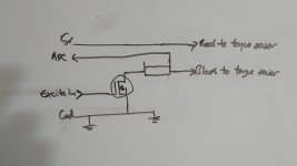
edit: Ok, can see how this might work - I need to use a mosfet to switch a pulse to excite the coil - then measure the current the coil draws with a shunt... I wouldn't need the cascaded mosfet arrangement we used for battery voltage since I'm only switching 5v - so a single high-side mosfet and a shunt hopefully... Please anyone with more than my rudimentary electronic knowledge chip in and give me some guidance :)

edit: do I measure the current on the ground side? I assume that's best then one side of the shunt is 0v - otherwise if I have the shunt on the positive side the each side of the shunt is higher than ground which is problematic to read without additional circuitry. I've always wondered why we measure current on the ground side - is this the main reason why or am I barking :)

edit: so something like this??

20221228_183836.JPG

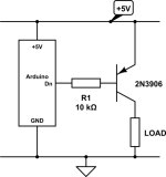
Or is a mosfet overkill - so something like this with a shunt in the negative side of the load?

u1iQ9.png
 
beemac said:
edit: Ok, can see how this might work - I need to use a mosfet to switch a pulse to excite the coil - then measure the current the coil draws with a shunt... I wouldn't need the cascaded mosfet arrangement we used for battery voltage since I'm only switching 5v - so a single high-side mosfet and a shunt hopefully... Please anyone with more than my rudimentary electronic knowledge chip in and give me some guidance :)

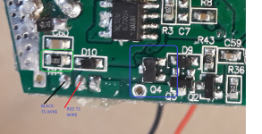
Really need a controller to gut and properly test the voltages and such - but can see that it does look like the circuit is broadly as I thought, but maybe with some additional bits for filtering or suchlike - see image below - shows the back of the board with the torque sensor wires - and what looks to be a shunt resistor (R44 - ringed in green) on the negative side - and a mosfet (Q4 - ringed in blue) with its drain connected to the red wire of the torque sensor.

The images are a bit shaky - but I think the resistor marking is '2001' which is 2K ohms. Hmmm that can't be the shunt resistor - seems far too high a value....

ts circuit.png
 
Since I remember, when I applied torque on the pedals, the square signal then got a peak like I did draw here - I hope you understand. So, the circuit to read the torque signal, needs to look at this:


I would say it needs a subtract circuit, to subtract the original no torque square signal. Then after, use an integrator (??) / low pass filter (??)...

-----------

And today, I got perfect motor control with VESC and the magnetic encoder on Bafang M500 motor:

[youtube]EL9Jek3_hDg[/youtube]

As on the current state, I only have the torque sensor and brakes sensors connected, I am missing the display, I still can quickly edit the Python code on my phone, changing the variable "assist_level_factor" where I can set a value like 1.0, 0.5, 3.0 or such (see next screenshot from my phone).
And as you can see, I can also quickly tune some parameters as motor max current, torque sensor min value, etc. This is the power of Pyhton and wireless programming:


And for the curious to learn, here is the main EBike code, that I consider almost finished and easy to understand:

 
beemac said:
Ok, can see the benefit from the point of view of not needing to build/flash etc. makes life a lot simpler - and I know it's something that's useful to learn, i'm just not sure I have enough time to start from scratch with python.
This Python is going crazy!! Now we can get automatic GitHub Updates Over the Air to our boards!! (more details)

Imagine that you update your code on your github, and then your Ebike board firmware get's automatically updated :D
 
casainho said:
beemac said:
Ok, can see the benefit from the point of view of not needing to build/flash etc. makes life a lot simpler - and I know it's something that's useful to learn, i'm just not sure I have enough time to start from scratch with python.
This Python is going crazy!! Now we can get automatic GitHub Updates Over the Air to our boards!! (more details)

Imagine that you update your code on your github, and then your Ebike board firmware get's automatically updated :D

I'm so far away from being able to code anything!

I'd forgotten how much 'fun' it was trying to get all the bits working.... I've replaced my mosfets on my dev board since my overvoltage situation and they just won't work properly for some reason - the 296 looks like it's switching ok but the 4140 just refuses to play ball - and I've replaced it twice so maybe all my mosfets are borked. In the end i've just bypassed them with a switch. There's also something wrong with the combined firmware build for the wireless controller - the bootloader part isn't correct I think. Using a brand-new nrf - when I flash the combined fw the nrf doesn't boot. I have to build and flash the fw for the remote first - then flash the fw for the wireless controller and it works at last.

So now I finally have my dev motor working again on the bench... :|
 
Ok, so now I can hopefully start playing with some code :)

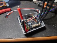
I gutted the controller that was on the bench when I had my overvoltage situation - the MCU still works if powered from the speedsensor - but the power stage is blown - so can't be powered from battery voltage and so the motor won't spin etc. Useful also to reuse the motor sensor and phase wire connectors. I've kept the PAS sensor in the case and extended the wires.

I checked the mini flipsky would fit in the controller case - and it does, perfectly! Good to know.

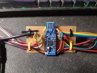
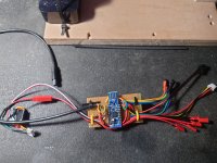
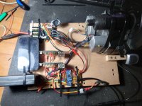
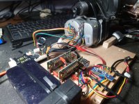
I decided to go for it and wire everything to an NRF before I start coding - so that I minimise the amount of later rewiring hopefully - got everything connected except the torque sensor. So I've got the PAS sensor, Temp probe, button pad, UART TX/RX to talk to the flipsky, motor hall sensors are connected to the flipsky, another UART TX to use as a separate debug console output, Jlink SWD - think that's all...

Oh I've just realised I've forgotten the wheel speed input - ah well, can add that later - maybe when I add the torque sensor.

Edit: Duh, I also forgot the brake sensor. If I'm not too hungover tomorrow I'll add that...

Hopefully the flipsky 5v regulator can cope with powering all of that, now to disconnect and carefully power everything up and hope I don't see the magic smoke!
 

Attachments

  • 20221230_181837.JPG
    20221230_181837.JPG
    2.7 MB · Views: 199
  • 20221231_135356.JPG
    20221231_135356.JPG
    2.9 MB · Views: 199
  • 20221231_135938.JPG
    20221231_135938.JPG
    3.7 MB · Views: 199
  • 20221231_145841.JPG
    20221231_145841.JPG
    3 MB · Views: 199
  • 20221231_145859.JPG
    20221231_145859.JPG
    3.1 MB · Views: 198
  • 20221231_145913.JPG
    20221231_145913.JPG
    2.2 MB · Views: 200
beemac said:
I checked the mini flipsky would fit in the controller case - and it does, perfectly! Good to know.
Amazing!!
And good work, seems you have everything in place but only missing the torque sensor circuit...

I will try switch to this ESP32 board, which is small and cheap, with the advantage to have Wifi for the wireless programming. Maybe we could work together on the EBike application. I plan to use the same application for my Xiaomi EScooter, the only difference is that I will use a throttle only and the motor also brakes, so I will need to apply a negative motor current.

I am planning to include unit tests on the EBike Python code, something I never did before. So I expect this code to be well structured and maintain it for next years, as I think using VESC + EBike board is a future prof solution for any future EBike or EScooter.

 
beemac said:
Hopefully the flipsky 5v regulator can cope with powering all of that, now to disconnect and carefully power everything up and hope I don't see the magic smoke!
My ESP32 board uses a lot of current, like 200mA from the 5V VESC, at it still works well. I am sure you will have no problems.

And, what is your plan about put the system in low power mode? when the EBike should be OFF at the user garage by several days / weeks / months ??

My best plan is for me to manual disable the switch I have on my EBike, that switchs on/off the "Smart Bluetooth BMS" I have. So, I must not forget to turn it off.
There is potential for the system to turn it off automatically, as another developer is already running this Pyhton code and communicate with the BMS by Bluetooth and is able to turn it off.
But I wish to have a better solution, something I could keep the microcontroller running and everything shutdown. The VESC from Trampa are very expensive and big, but at least they have ultra low power mode.
 
casainho said:
I will try switch to this ESP32 board, which is small and cheap, with the advantage to have Wifi for the wireless programming. Maybe we could work together on the EBike application. I plan to use the same application for my Xiaomi EScooter, the only difference is that I will use a throttle only and the motor also brakes, so I will need to apply a negative motor current.

I am planning to include unit tests on the EBike Python code, something I never did before. So I expect this code to be well structured and maintain it for next years, as I think using VESC + EBike board is a future prof solution for any future EBike or EScooter.

Yea I agree vesc+open source ebike board is a nice future-proof solution, that's what attracts me to the controller - and the scalability. If I want to build an electric car I can use the same tech more or less!

I'll make sure I code things in a way that's easy to migrate to a new board - keeping pin defs together and so on, and happy to work on ebike stuff together but for now I'm going to stick with the nrf as that's what I have and code in c++ as that's fun for me - and I also plan to reuse lots of code from the existing motor and wireless controller to get things going.

I'm hoping that just having a single board controlling everything - and so only one device to flash - with a single type of debugger should make the build'n'flash cycle easier - but if it gets frustrating that's the most likely reason I'll jump ship and move with you to a faster microcontroller.

casainho said:
My ESP32 board uses a lot of current, like 200mA from the 5V VESC, at it still works well. I am sure you will have no problems.

Ok that's good to know, I should be pulling much less than that.

casainho said:
And, what is your plan about put the system in low power mode? when the EBike should be OFF at the user garage by several days / weeks / months ??

Not really thought about that yet, way too much to do first - and tbh I disconnect both my bikes from the battery when not in use, so drain from the controller isn't something I've considered too much.

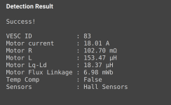
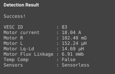
Just did a test with the sensors connected - works either way just fine - hard to say if the motor sounds better, it's so quiet I can't hear it over the bench PSU anyway!
 

Attachments

  • withsensor detection - tsdz2 - flipsky mini 4.2.png
    withsensor detection - tsdz2 - flipsky mini 4.2.png
    83 KB · Views: 793
  • sensorless detection - tsdz2 - flipsky mini 4.2 (2).png
    sensorless detection - tsdz2 - flipsky mini 4.2 (2).png
    81.7 KB · Views: 793
Back
Top