Kudos Build II

Hey guys, I have a question:

When you install a freewheel on a motor you can use a spacer between the side case of the motor and the back of the freewheel.

My crystalyte kit came with one and I used it on my first bike.

I've swapped it over to my new build and now I find the the freewheel is slightly tight against the frame.

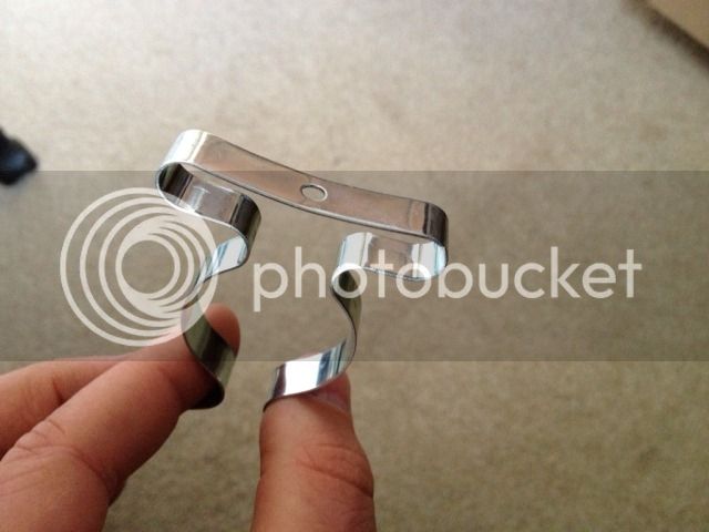
You might just be able to make out the spacer in this pic.

photo-4.jpg


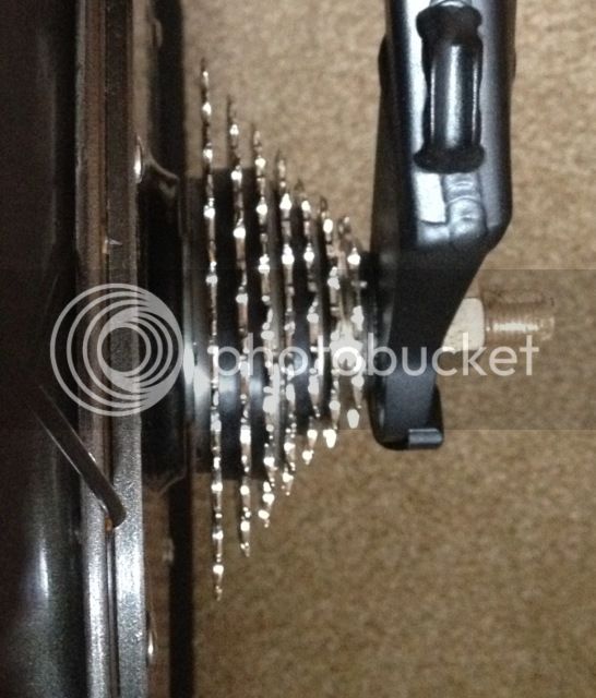
What I want to know is, can you safely remove this spacer and just have the freewheel stopping on the side of the case?

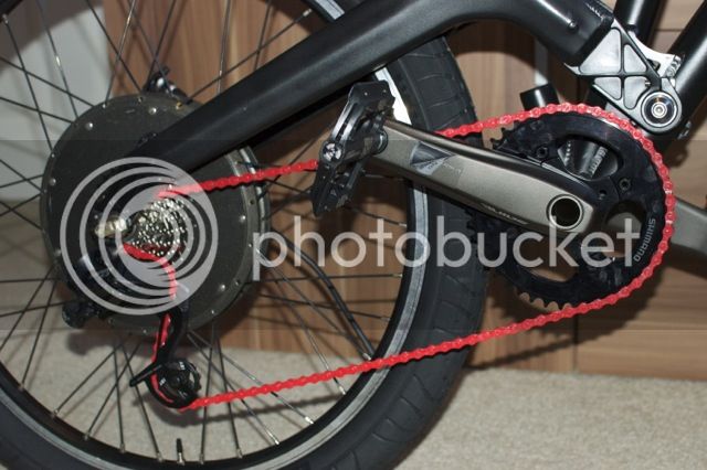
This will give me a bit more room and perhaps stop the freewheel rubbing on the inside of the frame dropout...

EDIT: Couldn't wait for an answer so tried it out without the spacer and seems fine. There's even a small gap now between the freewheel and the frame, maybe 1mm.

Cheers,
Kudos
 
I could not find a black 7 speed chain online, all sold out, my only option was to go red!

file.jpg


I think this will just be temporary until CRC get some black ones in......

Kudos
 
Hey man, I don't think you want your freewheel up against the inside of the frame,, I am pretty sure it needs the spacer so it can turn.

Nice Chain BTW :mrgreen:

Joe
 
Kudos your build is looking pretty hard core. I love the black look and that frame.

These seem like the type of issues I am going to when I do my phasor build. Still a newb
to all the parts to a bike other then the obvious one's so your build log will help me some.

Keep up the good work looks like you should see some light in that tunnel by now.
 
Thanks for all the comments guys! I appreciate some feedback now and then.

Well, I must have spent the best part of three hours last night trying to install my rear Avid BB7 brake getting more and more frustrated as the hours ticked by.

No matter what I did I could not get the caliper to align with the rotor. The caliper always ended up slightly offline with the rotor so would rub for about a quarter turn of the wheel.

Making things awkward is the fact that the inboard pad control that moves it in and out, is obscured by the motor, this makes adjusting it a major PITA.

I actually gave up in the end, but I think the next thing to try is adding a rotor spacer. Think I'll try a 2mm first.

It's odd because I've run into problems with this frame that didn't exist on my old Gary Fisher Wahoo hardtail, so it never occurred to me that I might need a spacer.

Kudos
 
Really liking the look of those hookworms with your frame. Very motard-esque. Bet they will have great feel and feedback too. I'm not jealous,.. really. :mrgreen:
 
A small update. After spending two evenings I finally managed to get my brake clippers on and aligned so that the rotors didn't rub. This is easily the most frustrating task I've had to do on the bike thus far. We're talking fractions of a millimetre here.

I tried to slide 1mm spacer between the side of the motor and my calliper but nope, that's how close they are.

It's a learning process. I've subsequently realised the reason why I've had such difficulty getting the calipers on and aligned is due to the fact that I chose the biggest rotors I could find 203mm. Yes they are supposed to give maximum stopping power, however it also means they suffer from disc warp more than smaller rotors.

This rotor warp means that the calipers have to be wider apart to accommodate movement. This in turn means that the standard Crystalyte ebrakes I'm using doesn't appear to have enough grab distance to allow the calipers to grip the rotor firmly.

I've tried to learn the skill of rotor straightening with some success allowing me to bring the calipers slightly closer together, maybe one or two clicks of the BB7 but still not enough.

So the next idea is to do away with the naff Crystalyte ebrakes altogether. I've ordered a couple of sets of Avid brakes which are supposed to be used with the BB7's. Hopefully they will have more grab and I'll actually have brakes that work!

Kudos
 
I have some 203 Promax rotors that im installing... Not the highest quality but it should work considering im recycling BB7 caliper. Im waiting on a post mount to 203 post adapter. With the 160mm rotor It was a pain to get my BB7 centered correctly. As you said i could get it down to about two clicks but my stopping power was alot better that what you describe.. Make sure your pads are clean and the rotor is clean. You may try the park tool disc rotor straightening tool.

I do understand you concern with the levers. Ive been looking at mine and trying to figure out how to go back to the stock intended levers but the value of mixed regen and regular brakes is to valuable to loose. You may want to consider repurposing a horn switch for push button regen.
 
Well I got my Avid FR-5 brake Levers, slapped them on and now the front brake is all good. There does appear to be more grab.

The bad news is that after some more hours of my life I won't get back, I just could not get the rear rotor straight enough to work well. I'm going to chuck it.

So I've given up on the 203mm rear rotor for now and ordered a 160mm. I know icecube57 said he found this awkward too but we'll see how I go.

There is always 180mm and 200mm is this fails.

Kudos
 
I just couldn't give up on the 203mm rotor so I bought another one, an Avid G2 Clean Sweep and tried it out, same problem only worse.

Having a bit of a low with this build now. I've probably spent around 14 hours just trying to align the brake caliper and I'm still no where near.

Something I have noticed, is that when I rotate the wheel it's not just the caliper that moves left to right. The space between the caliper bolt closest to the side of the motor and the motor itself seems to shrink and increase too. Only slightly.

It's as if the axle is not perpendicular to the bike centre line and so is turning slightly offset. The axle does seem quite loose in the dropouts.

I don't know if there is anything I can do about this?

I still have the 160mm rotor to try but I don't have the appropriate mount for that yet.

Kudos
 
Cargo_Tom said:
Aw that sucks man. Am I reading you correctly that the motor hub itself is not true?

Yep that's what it looks like.

I put a standard wheel on to check and it's perfectly straight.

So I put the motor back on and attempted to do some checks and it's definitely not rotating true.

I'm still trying to determine if it's just the side that freewheel attaches to or if it's the whole Motor.

I've never heard of this happening before?

Kudos
 
I think I read a post somewhere about the hubs themselves leaving the factory out of true sometimes.

If you know someone with a metalworking lathe, they might be able to true up the disk contact surface of the hub, assuming that particular hub axle sits perfectly straight in the dropouts. Or it might make the problem worse :/
 
Ditto Cargo Tom's sentiments of that sux re wheel not true...

I have no idea, just a suggestions, but could you possibly torque down the appropriate bolts on the disc side side cover to get it closer to true... tighten down the cover nuts that are where the disk rotor is AWAY and loosen where it is close...

Again, just a thought, I have not tried this...

Joe
 
OK Between me and a friend we have come up with a plan!

I'm going to attach a dial gauge to the frame so this will show me precisely how out of true the motor is.

Then I will unscrew the side plate slightly and tap apart the case all around until it is trued again.

I will then use a feeler gauge to measure the gap I've made and create a shim out of brass or stainless shim material.

Kudos
 
OK after many more lost hours trying lots of different ideas, I ended up cutting a piece of coat hanger wire into a right angle shape, fixinging it between the axle bolt and washer, then bending it such as it hovers just above the rotor.

This then gave me a fixed point to work from, so looking from behind, as I rotated the wheel I was able to tell out true the rotor was. I then used a small pieces of cereal packet cardboard as shims and wedged them between the motor and the rotor.

Doing this enabled me to take the worst of the wobble out. It is still no where near poker straight, but the left to right movement of the rotor was lessened to a point where I could attach a caliper and still have enough grab on the lever so the brake actually works, even if I have to pull the lever all the way in.

This motor was always intended as a temporary measure. I wanted to have a motor laced into another halo sas rim like on the front ( at great expense!).

So now onto the torque arm....

Kudos
 
AEAD19B2-DCAB-4A18-AC82-BF61CEDB939F-584-0000004E4170E5A8.jpg


Just considering a torque arm now.

I'm planning on running this bike at 82V 40A so peaking just under 3.3KW.

I've seen plenty of bikes at this power with a single off the shelf TA, Jimbos' bike springs to mind.

I can't find the exact dimensions ( a template would be really useful ) for the front torque arm as sold by ebikes.ca and crystalyte Europe, but it might just fit my situation with the attachment to the bike being the rearmost brake mount bolt.

Does anyone know where I can get a template?

Failing that can anyone tell me the exact distance between the centre of the holes of a brake mount?

I might have to fab a custom one somehow.

Cheers,
Kudos
 
I took a chance and ordered the front torque arm from Grin seeing as there is a handy eyelet for the brake attachment and it fits!

0C5A2EF9-56B9-4CFD-923C-1597623EF2CD-13417-000005E45434F924.jpg


I think it's the first bit of luck I've had on the whole build :shock:

I still had to drill out the eyelet hole on the TA, i think it was only 4mm but needed to be 6mm.

Should probably paint it black....

Kudos
 
Found these at the hardware store, might come in handy to mount the controller.....

067B360C-F153-476A-8882-B91DDC1A9625-6649-00000154DFE4BCC1_zps7b933ab9.jpg


Kudos
 
kudos said:
Cargo_Tom said:
Aw that sucks man. Am I reading you correctly that the motor hub itself is not true?
Yep that's what it looks like.
I'm having a similar problem with my Xtracycle build. The result is super annoying brake squeal. Don't know if its the boss, the adapter, or the axle, but I suspect it has to do with how the hub motor axle just fits the dropout and so won't go all the way up into it. It's about 1mm low--still in enough for the anti-torque washer to engage, but not quite flush with the top. I suspect that since the dropout was not designed for such a close-fitting axle, the two sides are not quite the same, and it's giving a small angle from the vertical. I'm reluctant to use a file on the dropouts, since I don't want to introduce even more asymmetry.

I'm trying to solve it with DIY shims between the adapter and caliper made from heavy duty aluminum foil (might be a wee bit better than cardboard :) ). I also have some 0.0005" SS feeler gauge material I might try.
 
I used Aluminium foil at first too actually, which also worked well, I just found it kept compressing and falling out when I was trying to fettle it.

I'm still not sure exactly what the problem is with my wheel, I have a suspicion though it's the axle because only that would explain what I'm seeing.

Good luck thickhead.....

Kudos
 
kudos said:
I used Aluminium foil at first too actually, which also worked well, I just found it kept compressing and falling out when I was trying to fettle it.
True. I'm using a teeny dab of lock tight to hold them. So far it works... meh. I still have to futz with it some more since the squeal is diminished but not gone. Oh, and thanks for that enginerd term "fettle"! Three+ decades as an engineer, and it's new to me (probably cuz I'm more of a theory guy than a designer).

kudos said:
Good luck thickhead...
Thanks, man. Back at you. Looks like it's gonna be a great bike.
 
Back
Top