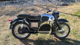
My first EV conversion: '69 Honda CA160 "Baby Dream"

mannydantyla

100 W
Joined
Dec 4, 2020
Messages
127
Hi guys!

I'm converting a Honda CA160 to electric and I'm going to need lots of help and advice from this forum because I've never done anything like this before. I have experience with electricity but not with high voltage batteries and electric motors.

I'm putting the project on youtube and here is the first video:

[youtube]FtBMTKIRqpQ[/youtube]

PLEASE watch the part about the motor selection and let me know if I am right or wrong!

Too Long/Didn't Watch: I'm not sure that the 3kw QS hub motor will be fast or powerful enough. Here's why: this calculator says that I need an RPM of 730 to reach 50mph with 23" wheels. The QS motor specs say that, in the high speed configuration, it can do 830 rpm which is good for 52.8mph with 24 inch wheels. When I put that wheel size and speed into the calculator, it says that the RPM would be 739. Which is just barely fast enough....?

Would that be pushing the motor to the limit? The bike is for my wife to ride around our little town and I don't think she will mind if the top speed is actually only 40 or 45. But if she wants to keep up with my 200cc motorcycle then the top speed would need to be 50mph.

And would 3kw (continuous) be powerful enough? I just don't have any experience or understanding with electric motors and I don't know what 3kw would feel like in terms of torque and horsepower. The original 160cc engine was rated for around 16hp iirc. It would be awesome if it was quicker than the original bike but I also don't want it to be an accidental wheelie machine.

I'm thinking about using these or these LiFePO4 batteries and if I assume that the seller is inflating the discharge current by 1.5 then here's my math for 13 [edit: 23] of them wired in series for 72v:

  • continuous current = 50 amps = 3.6kw @ 72v (nominal) and 4.15 kw @ 83v (max charge)
  • max current = 83 amps = kw @ 72v (nominal) and 6.9 kw @83v (max charge)

So even LiFePO4 batteries with their (relatively) low power-density would continuously provide more power than the motor can use (controller would limit this, right?) and peak power on a full charge would also be more than the motor's rated peak power. So would a 4kw motor make more sense?

Am I doing any of this math correct? If so, then is the 3kw hub motor too small. Am I worried too much about all the theoretical numbers?

Thank you everyone!!!
 
My good ole' internet barely loaded this page, can't get the video playing.

So just hazarding a guess:

NO! ABSOLUTELY NOT! Forget 3kw. How far are you trying to go 50mph? Then not recharge before heading home? Batteries, batteries, batteries. That bike will be heavier than you think. The calculator is optimistic to begin with. A 3kw motor is about like an 80cc 2 cycle engine that doesn't take that little dirtbike to 50mph in most cases.

With my web problems I'm not going to try to look up the Honda Dream, but 16hp from a 160cc sounds optimistic, but if that is right than the equivalent is a 12kw motor, though electrics have a way of out performing what they are supposed to be equivalent to. Will enough batteries for the range you want make it heavier than before the conversion?

I'll let someone who can see the video and maybe even worked with similar before take it from here. But I'd guess you'll be wanting 8w and up for your purposes.
 
I'd go with a QS hub motor with a 50H (QS273?V3?) if its 6-8kw but you need to confirm the rear dropout width of the motorcycle and the hub. Otherwise go with a mid motor, chain setup like a Cyclone 16kw with a Sevcon, Sabvoton, Nucular at say 72V 30Ah and see how far that gets you around town, then add additional battery firmly in place for any extra distance you want.

http://www.qs-motor.com/product-catagory/motorcycle-wheel-motor/page/4/
http://www.qs-motor.com/product-catagory/e-bike-motor/

The key is a powerful controller, choosing the right motor for the terrain and any hills.

Otherwise just go out and buy a ready to ride bike, cheaper and easier for a gasser then electrons.
 
It dosent sound like you have read much about other builds.
I suggest you read this thread: https://endless-sphere.com/forums/viewtopic.php?f=12&t=90032
It should be rather similar to what you plan.

Edit, I watched the video and it seems I have to take back that you havent read about other builds :wink:
But maybe not the right ones, I still think you should look at the one I linked. I dont mean it is similar in appearance like the ones you have looked at, but similar in ev parts. And actually used and tested.
 
Alright thank you everyone!

Rear dropout width is 189mm. I believe the the 4kw hub motor could be made to fit with just a little squeezing, based on another thread on this forum with a very similar bike. They'll have to be heavily modified anyways to hold the hub's axle which is a lot different than the old wheel's axle. Not a problem.

I'll check out that Ninja 250 build, I haven't seen that one. I've done a lot of book reading, internet researching, and youtube watching but I still have more to learn of course.

There is a large hill I would need to get up if I wanted to commute with it to work, which will hopefully start happening again if this pandemic ever ends. But the commute would be very short, around a mile in each direction. The hill is steep enough that I can't pedal up it unless the bicycle has a super low granny gear.

Range does not need to be much and I could sacrifice some range if it means saving weight and space. 20 or 30 miles of range would be enough.

Thanks again.
 
mannydantyla said:
Rear dropout width is 189mm. I believe the the 4kw hub motor could be made to fit with just a little squeezing, based on another thread on this forum with a very similar bike. They'll have to be heavily modified anyways to hold the hub's axle which is a lot different than the old wheel's axle. Not a problem.

The QS dropouts are typically 200mm (newer 14kW motors are slightly wider).
Any "squeezing" will need to happen on the frame side of things.
 
Some previous discussion about this project, with info regarding a number of important things, is here:
https://endless-sphere.com/forums/viewtopic.php?f=12&t=106406&p=1602514#p1602514
and can be moved to this thread if desired (but it will show up *before* the first post, so that new first post will need to be edited to add the project summary or whatever the OP desires).
 
mannydantyla said:
T When I put that wheel size and speed into the calculator, it says that the RPM would be 739. Which is just barely fast enough....?
If you want quick acceleration, especially at higher speeds, you may need a motor capable of much faster speed than you actually want (or a controller and battery capable of much higher current than otherwise). Then just do what you would always do, and use the throttle to control actual speed. ;)

This is why a number of years ago Justin_LE sent me a faster winding of motor than I would have chosen for Crazybike2, and it worked--had quick accleration all the way up to max desired speed, where with the motor winding I wanted, that would've just made it slighly past my max speed at the voltage I was running at, it would have been sluggish as it neared top speed, and been worse over the ride as the battery discharged, and it wouldn't have done what I needed it to do.


Also, if you *had* to go faster, for instance to get the heck out of the way of someone in traffic that does something unexpected, where slowing down instead is not a usable/safe option, having the extra speed (and still having quick enough acceleration *at* that speed) could literally be a life-saver.

The https://ebikes.ca/tools/simulator.html will help you see how this works, if you read the whole page to learn how it works, then play with various systems and setups/environments.


Also, make sure the RPM they provide is under a load. If it's a no-load RPM, you may only get around 80% of that RPM when actually riding.


And would 3kw (continuous) be powerful enough?
The simulator will help you see how much power is needed for various speeds vs various system/bike configurations, as well as how much wh/mile it will use up, and that will help you get your battery sized correctly.

FWIW, a motor can do (for short bursts) quite a few times its' continous rating if you need it, like for acceleration from a stop to cruising speed, etc. Many motors can do more than their continous ratings for quite a while, to one degree or another (but some are barely able to handle their continous ratings, depending on the wheel size they're in).


I'm thinking about using these or these LiFePO4 batteries and if I assume that the seller is inflating the discharge current by 1.5 then here's my math for 13 of them wired in series for 72v:
Well, first, one of those doesn't even say what it's discharge rate is. The other only lists a *max* discharge, but not a continous one, so you don't know what it could actually handle. I would only recommend a cell that you can get a manufacturer (not a seller!) provided discharge curve for, preferably one that has already been independently verified by someone testing them (like say, by building a pack from them and testing over time, or by doing lab testing). But at minimum, an actual spec sheet from the manufacturer showing discharge and charge curves at various current levels.

FWIW, I wouldn't even trust the company selling the green cylinders--their page lists the chemistry of these cells as three different types in different places, each of which would be a completely different voltage range and charge / discharge rates for that size cell. So you can't know which information on that page is correct, and which is not, and you can't trust that whoever you ask at the company will actually know which is right or not, or that they will be able to tell you correctly even if they do.

The company selling the blue box cells says in one place they're 1C charging *max*, but then they also give a 2C charging time, which would be charging at twice as much current as the cells are capable of handling (and could thus cause damage or even a fire, if they are indeed 1C max charging rate cells).

Let's assume you used the 25Ah that says it's 3C max. Assume you have to cut that by 2/3 for the continuous current (you might get half, rather than only 1/3, if you're lucky), so call it 1C. That's only 25A continous, with a peak of only 75A (which is probably only a few seconds without heating the cells up, and will probably have serious voltage sag while under this load).

If you used the 30Ah cells, and assume the same C rates, you get 30A continous, and 90A peak.

Next, youll need a lot more than 13s to get 72v nominal. At 3.2v (LiFePO4) then you need 72v / 3.2v = 23s (have to round up from 22.5; you might want 24s instead depending on BMS used). 13s will only get you about 41v.

For worst case power usage planning, let's assume you need 4kW continous (you probably don't, but better overkill than underperforming and having to buy new parts to make it do what you want ;) ). FWIW, you never want to plan power usage around the full charge voltage, but rather around the average voltage, otherwise you *only* have full power available at full charge, which won't last long, especially with LiFePO4 (they quickly fall from full to average voltage, then sit around average until they are almost empty and then quickly drop to empty). So: 4000W / 72v = 56A. For a 25Ah cell, that's a little higher than 2C. For a 30Ah cell, that's a little less than 2C. If the cells can really handle 2C, then that's ok. In the possible but unlikely event that they're really only 1C to 1.5C cells, you'd need to double up the cells, paralleling two sets together for 23s2p, or using 46 cells total, to get 4kW out of the pack.


Now, think about capacity (range). 23s1p would only be 72v 25Ah (or 30Ah), whcih is 72 * 25 = 1800wh (maximum! you probably wont' get all that due to various losses, and that's also only when it's brand new..so assume 1500-1600wh usable out of that, with margin for error / aging / etc). A 30Ah pack would get you 72 * 30 = 2180wh (you could assume 1900-2000wh usable).

If you only need around 50wh/mile, then 1500wh gets you about 30 miles range. If you run into even small headwinds, or long enough small hills or steep enough big ones, or a lot of stop/start traffic, power usage could go up dramatically. If it went up to 100wh/mile, that drops your range to only 15 miles with 1500wh. You'd get more with a 30Ah pack, but not a huge amount more.
 
Thank you very much amberwolf.

I have decided that the 4kw motor would be a wise choice for this build. I could agonize over this choice for days on end, or I could just go with the larger of the two motors and be done with it. Can't go wrong, right? Might not be exactly what I want but it will at least be fast enough.

I think this is what I need: http://www.qs-motor.com/product/4000w-spoke-hub-motor-for-electric-motorcycle/

However I'm having some trouble communicating with QS. Probably my fault. I first sent them an inquiry about this conversion kit (which I now know/think is not the right product) but I asked if it could be laced with spokes to a 16" rim. Someone named Nick replied, said yes it can be made to fit a 16" rim, and he asked me what the fork width is. I said 190mm, he replied that 200mm is needed and so it wouldn't fit and that was the end of that. I replied that the width was not a problem and that I actually need this hub and he just replied "can't make 16inch rim." Even though the web page says it is for a 16" to 26" rim.

I started a new inquiry (from the correct webform this time). That was a few days ago and I'm still waiting on a reply. Fingers crossed.

While that was going on I thought I would investigate the possibility of a mid-drive motor in the hole in the frame. My concern was that it was too far away from the swing arm pivot point, which would cause the chain to be too loose when the rear suspension is compressed. So I used a tie-down strap to compression the suspension and find out and sure enough, the chain was obviously too slack.

screen_shot_2021-01-04_at_12.05.28_pm.png


Could a spring loaded chain tensioner help? In my experience, they're problematic. For example, if you're gassing the throttle while the suspension is compressing, the torque on the chain will easily overpower the spring in a spring-loaded chain tensioner.

Plus I kind of hate the OE rear wheel, it's just a pain in the ass, need to disassemble it to get it off the bike, and reassemble it to get it back onto the bike, including the bearing and races. Not a good design at all. After I took it off and put it back on, there is now something obviously wrong with it and makes a terrible noise when spinning, so I clearly did something wrong. But there is a rubber coupling inside the hub that cushions the chain jerk during take off, that might be nice though for an e-bike with a lot of torque. And the rim isn't too rusty.
 
This could be interesting: http://www.eastgem.net/gearbox-200.html

Would be an easy(er) replacement of the ice engine and looks pretty cool too. As far as I understand, it would allow for smaller battery packs. Right? But with weird shifting issues, added weight, and added complexity and reliability issues. Torque for days though!

Maybe.... more reading is needed.
 
I ordered the hub motor! I made a new inquiry with QS and this time I got a response from Robert and he was very helpful. They were able to lace their 4kw 205 motor to a 16" rim (1.85-16), so I got that with the matching controller (KLS7245N), their disc brake kit, and their cheap twist throttle.

Now I can start thinking about the battery and start to digest amberwolf's help.

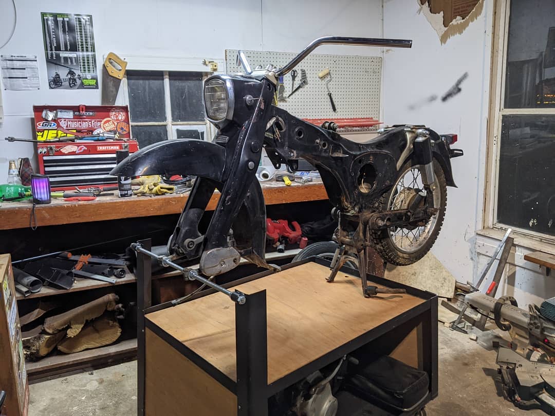
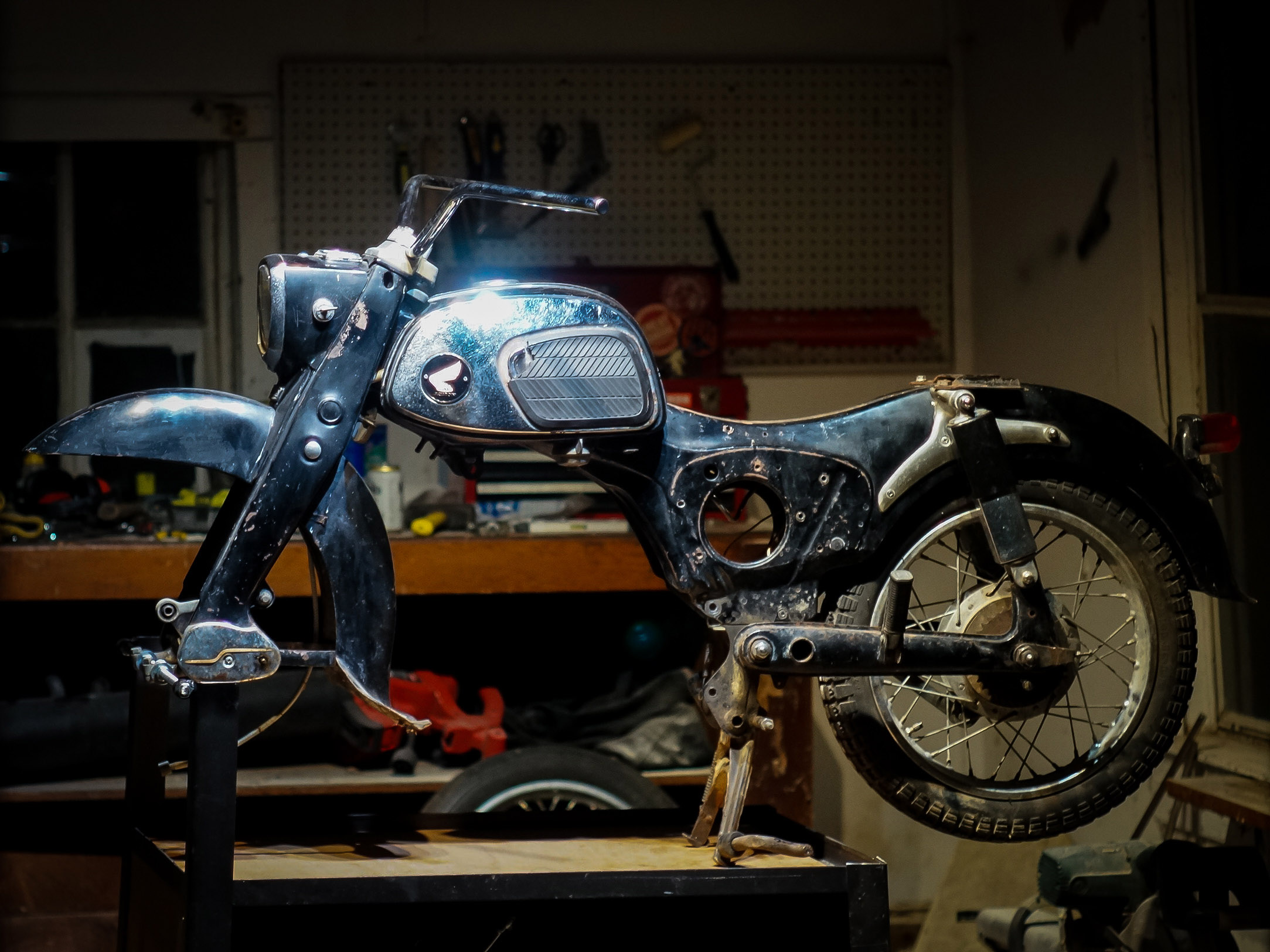
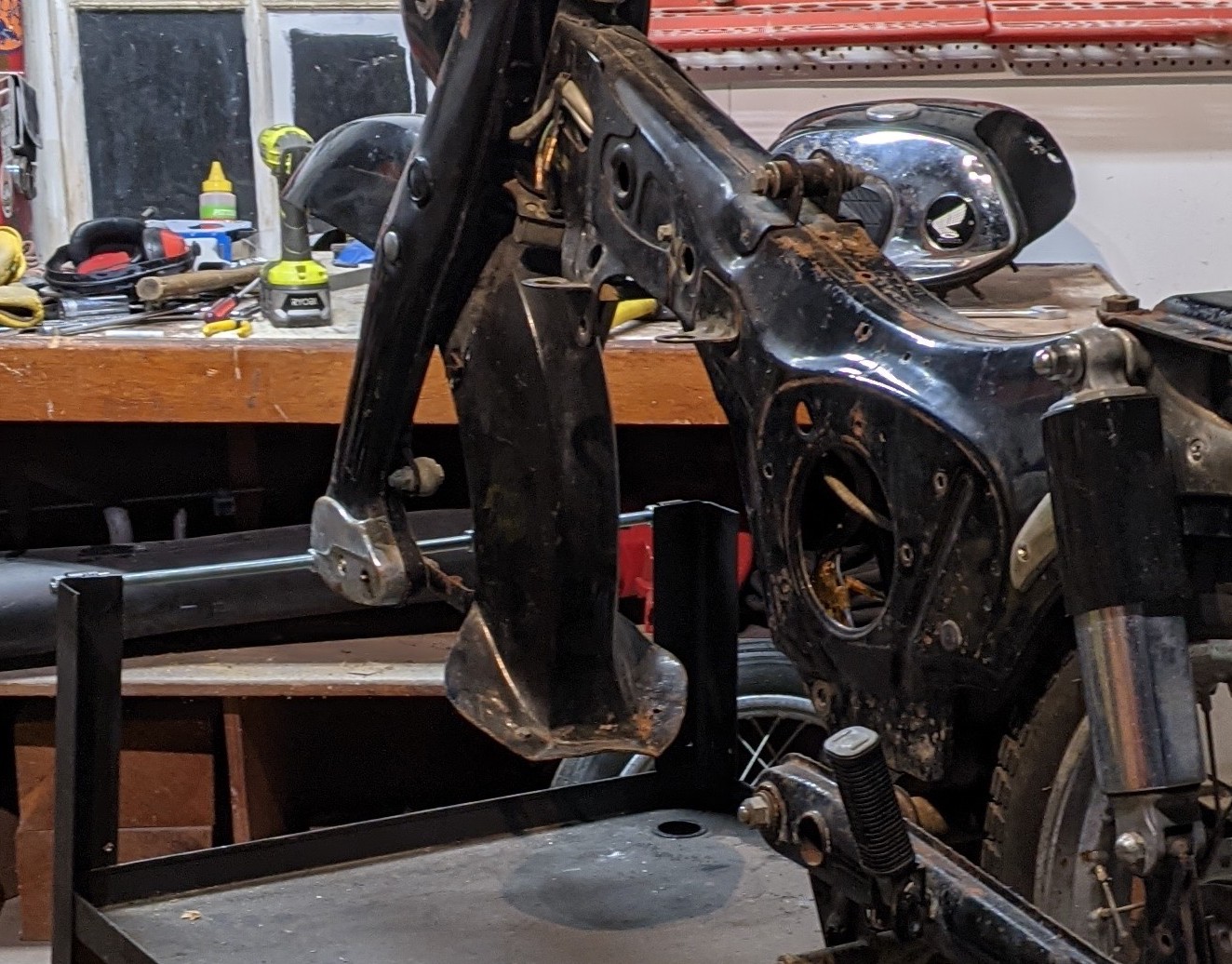
Yesterday I built a special table to stand it up on. Would you call this a frame jig? Or a chassis fixture table? Or just a custom motorcycle stand? I don't know but I like it a lot and it will make everything a lot easier and more enjoyable.

135759125_405701557349575_2251753623476808812_n.jpg


DSC07859.jpg


And because this is the "E-Scooter and Motorcycle Photos & Videos" forum, I better add some more photos. You would have seen these if you watched the youtube video I posted in the first video though.

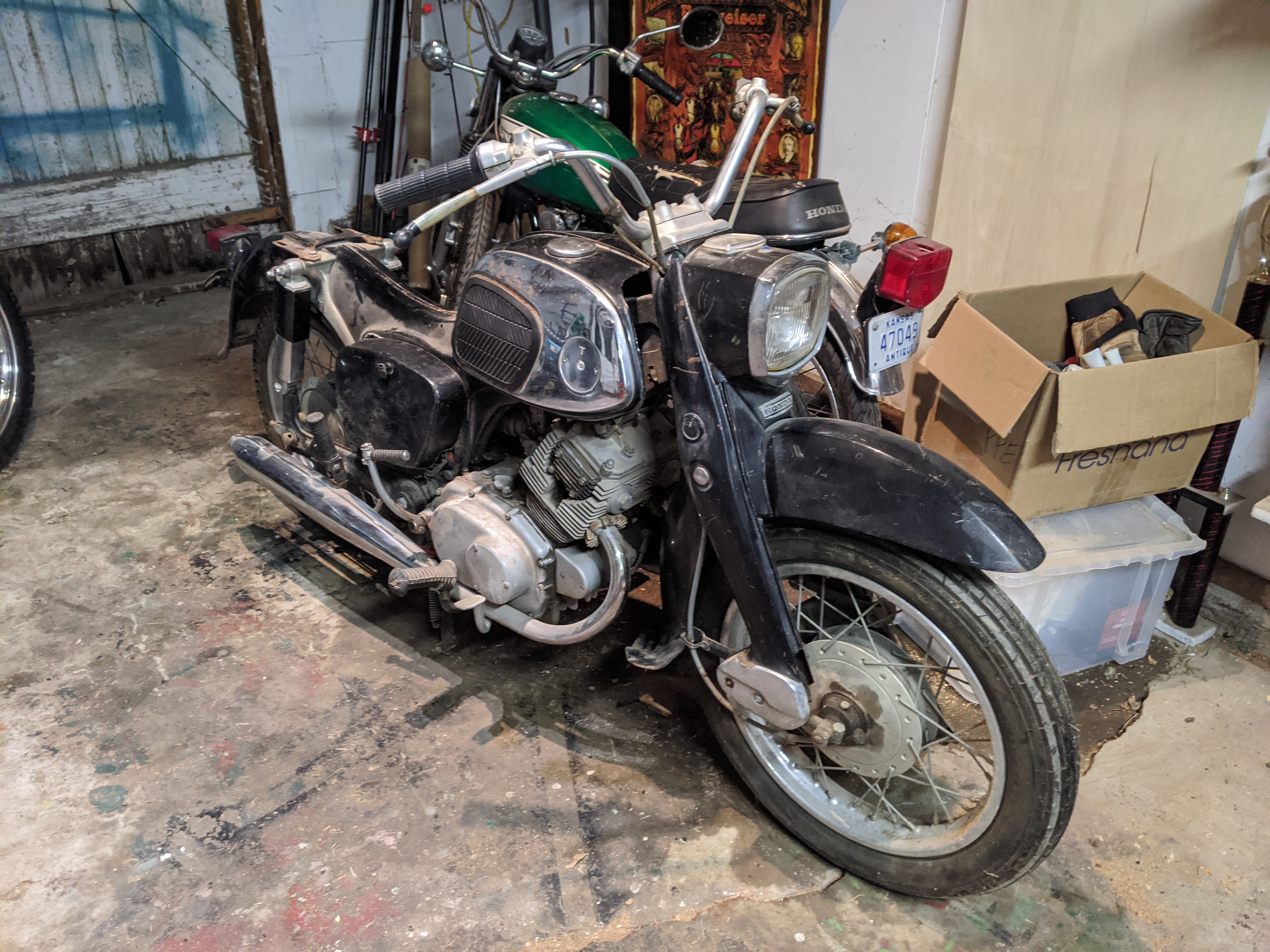
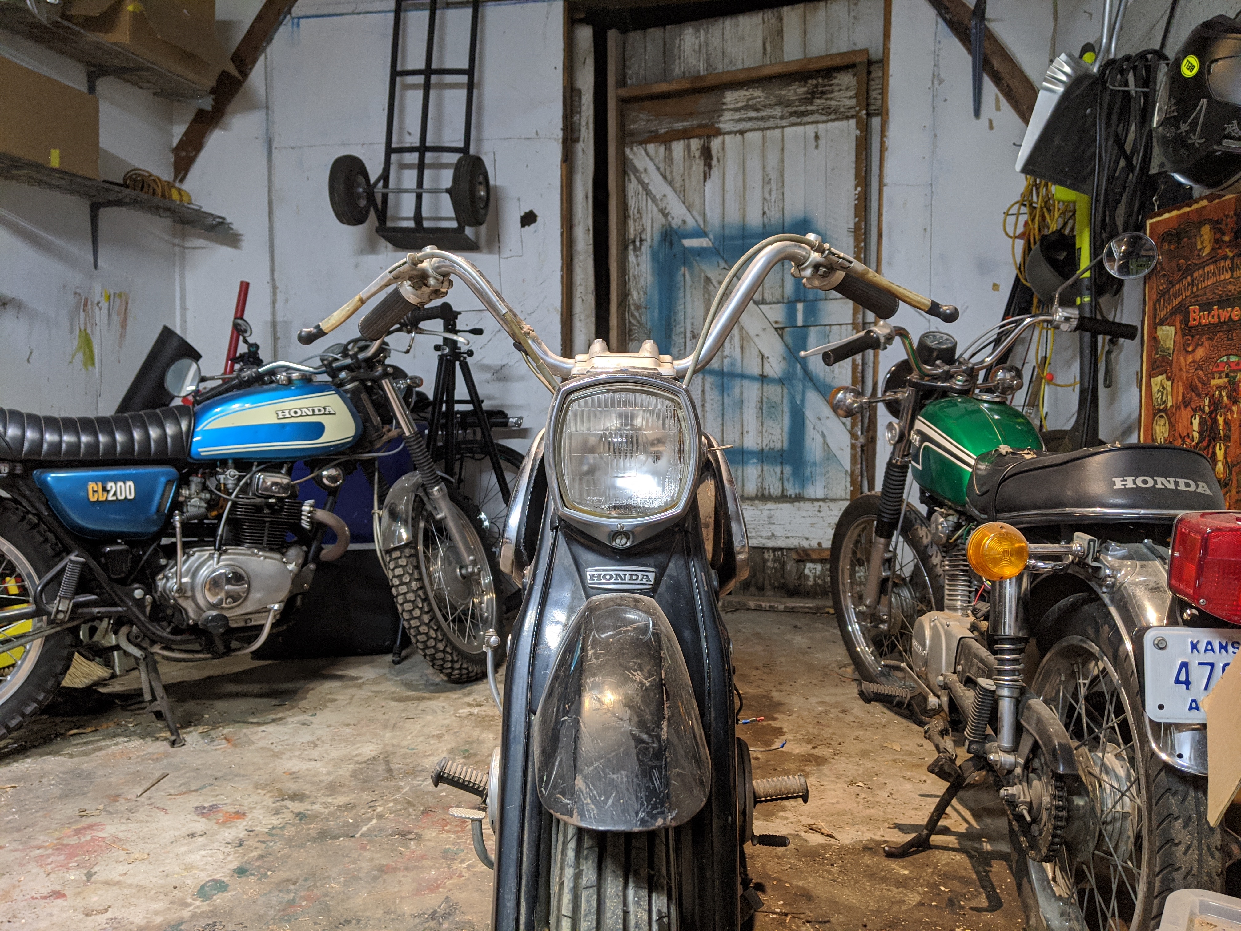
The bike the day I brought it home:
IMG_20201125_212715.jpg


IMG_20201125_214507.jpg


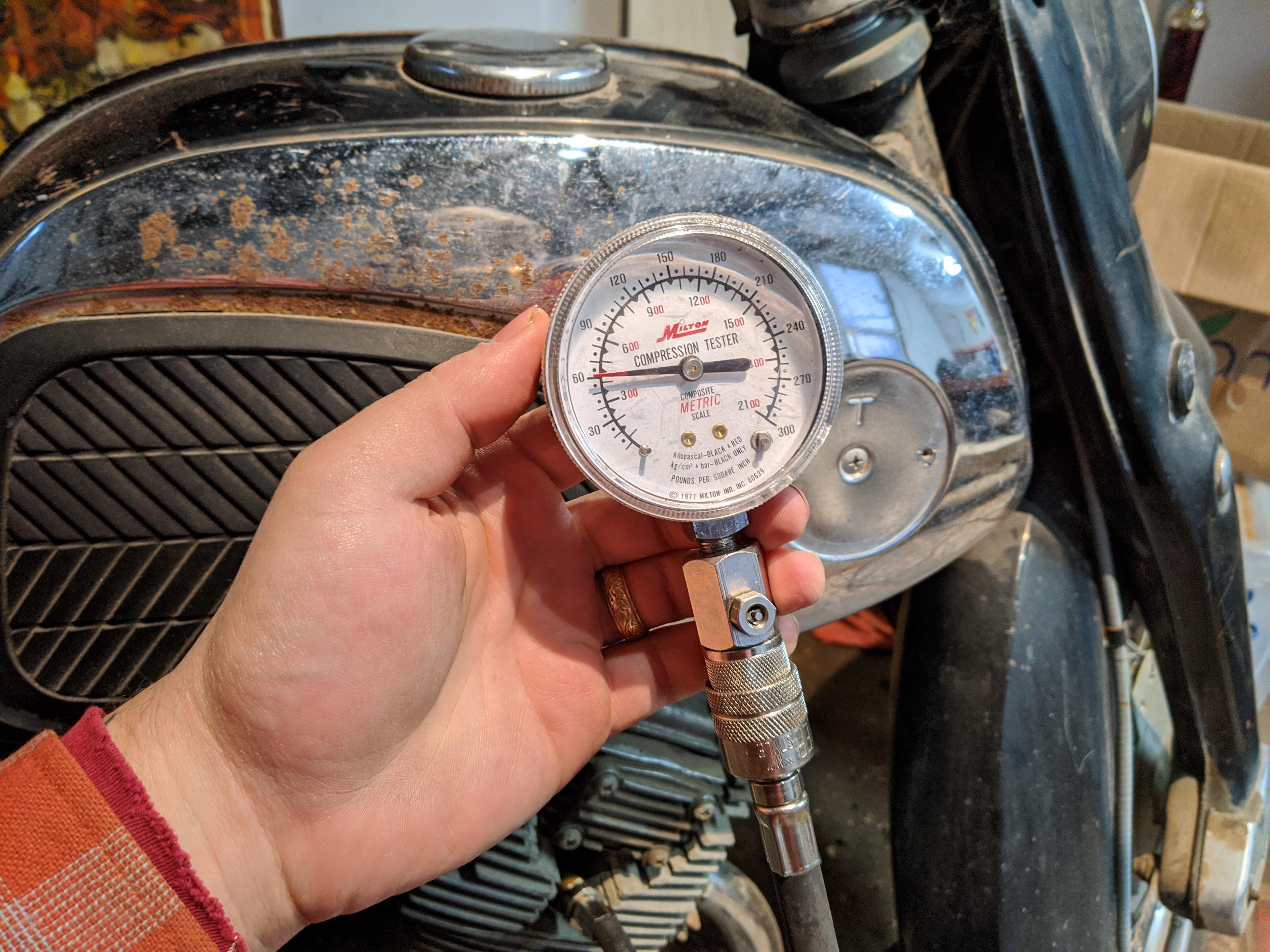
Proof that the gasoline engine was in terrible shape:
15hvf32q69361.jpg


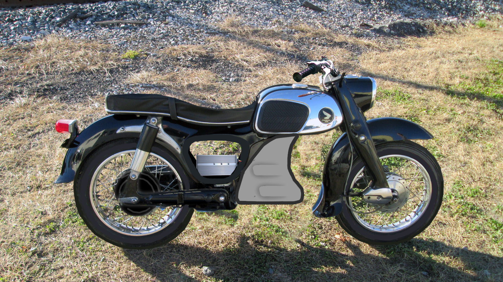
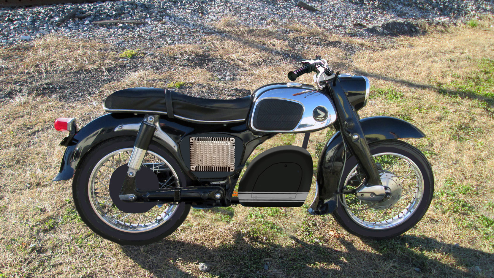
Mockup of what I want it to look like after the conversion:
CA160%20EV%20mockup%202.jpg
 
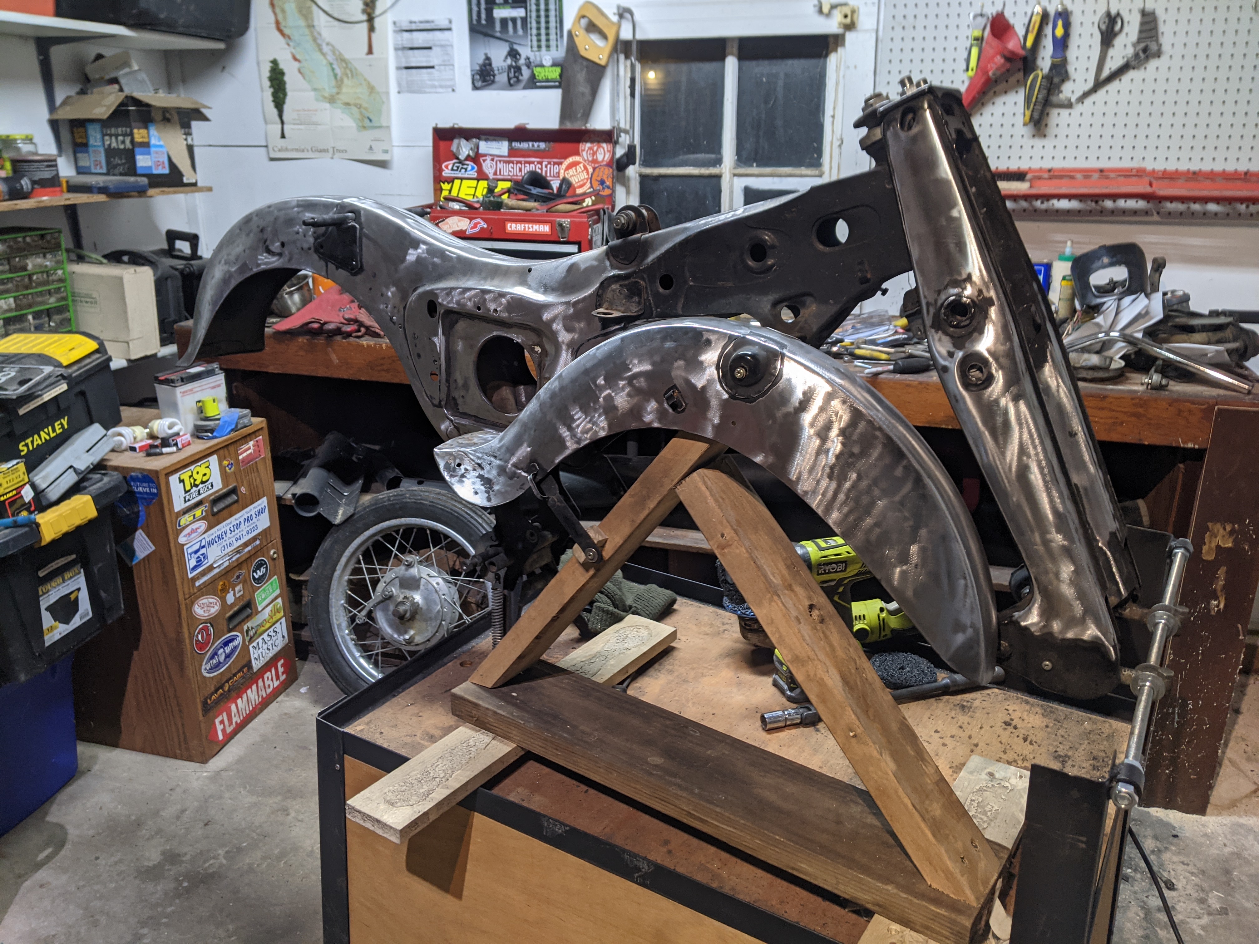
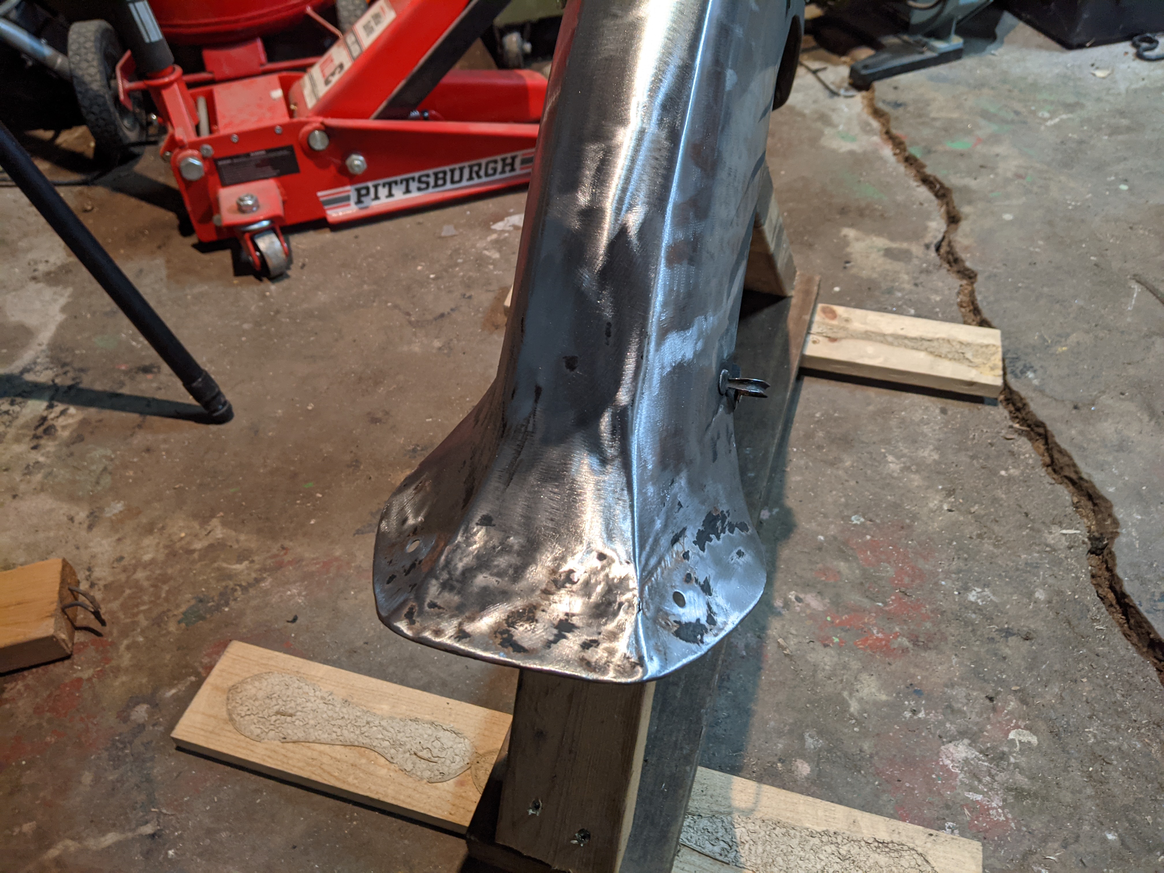
Still waiting on the motor to ship (they haven't even sent me a tracking code yet) so I've busied myself by starting on the body work (something I know how to do!). I got all (most) the paint stripped off by using a paint stripping disc on an angle grinder, it worked really well.

PXL_20210112_004834635.jpg


The front fender's "bell bottom" flare had some pretty bad damage, like it got folded upwards after riding over a curb or something.

PXL_20210107_011917609~2.jpg


I was able to get it mostly corrected with a hammer and dolly. Will still need a good dose of body filler though.

PXL_20210112_004938277.jpg


Next I'll add the bondo to where it is needed, sand it smooth, fill the pin holes, then etching primer, then sanding/filling primer, sand it flat and smooth again, then etching primer on any bare metal after all the sanding, then the color coat of paint, and then the clear coat. For this project I think I will pick up a cheap air gun from HF and order some 2k paint from Eastwood or something. Will be my first time painting anything other than with rattle cans!

I've also started thinking again about the battery pack. Now that I know the motor size, 4kw continous, I can calculate what discharge rate I'll need from the battery to match the motor. 4000w / 72v = 55 amps. I need a battery pack that that continuously discharge 55 amps. Right?

And I've also been planning the controls and the wiring harness.

I want the controls to be set up like a bicycle. Front brake on the left handlebar and rear brake on the right handlebar. The headlight will always be on (no high beam switch either). And the bike did not come with turn signals but I'm adding them for sure. Just need to find a turn signal switch I like.

I'll also need a keyed switch that will turn the bike on and off, and a kill switch that can quickly shut of the motor in case anything goes wrong. I also would like the brake switches to connect to the motor controller and tell it to not spin the motor if the brakes are engaged. Another safety feature. Actually, I think a feature of the motor controller that I ordered (Kelly KLS7245N) is regenerative braking and there's multiple modes to select from and, if I'm not mistaken, one of modes is to have regen only when the brakes are applied. That is what I would select. But what would happen if the brake is applied when the throttle is non-zero?

For the headlight, the old sealed beam is 6v so that will not do. But it is a unique square shape so I will not be able to find a 12v LED replacement (I think). So my plan is to take it apart and retrofit a LED light of some sort inside of it. I found a tutorial on how to do this, but all the images are missing. Thankfully though the description is helpful enough that I should be able to figure it out.

Once I have all that figured out then I can start designing the wiring harness and then start actually building it.

Question: does the 12v system's ground need to be isolated from the chassis?

Thanks!
 
This is pretty awesome. Basically you are doing exactly what I am doing, motor, controller and all. Only difference is mine is a Vespa, but basically the same. I even ordered from Robert. (No shipping notification yet either.)

Take another look at my wiring diagrams. I have completely isolated both the motor controller circuits from the frame ground, and the 12V converted power from the frame ground. The 12V part may not need it, but if there is a short in the 72V system it could fry the 12V system, so I chose to run grounds separately.

By the way, have you seen this video series? Very applicable to your build: https://youtu.be/SSwobkeQivU

And this is also applicable, and way over the top: https://youtu.be/gYs_jYUyaoY
 
Yup, I've seen both of the videos.

The video from ebikeschool, I'm very upset that he hasn't finished the build yet! Probably running into issues with the rear shocks after he widened the swing arm so much. I might have to widen my swing arm by a mm or two but there's another thread here on Endless Sphere with nearly the same exact bike (early 60s honda Benly) and he's also using a 4kw QS motor and he had no problem with it fitting into the swing arm. I'm also anxiously waiting for him to finish his build so I can see how fast it is (shoutout to MACK, if you see this then please give us an update :) )

And there's yet another guy building a small Honda cub with a 4kw QS hub motor, on youtube shearch for SmallGuyLittleBike, but it appears that he too has abandoned the project!

That's why I was glad to find your project on here but you're only a a little ahead of where I am at
 
Yeah, I think he got in over his head on the mechanical side. Too bad, I like his work and videos. He has posted a bunch of other content since then, so he is still around and active. On the shocks, all he really needed to do was angle his mounts about 5-7°and he would have been ok.

Thanks for the link, very cool.
 
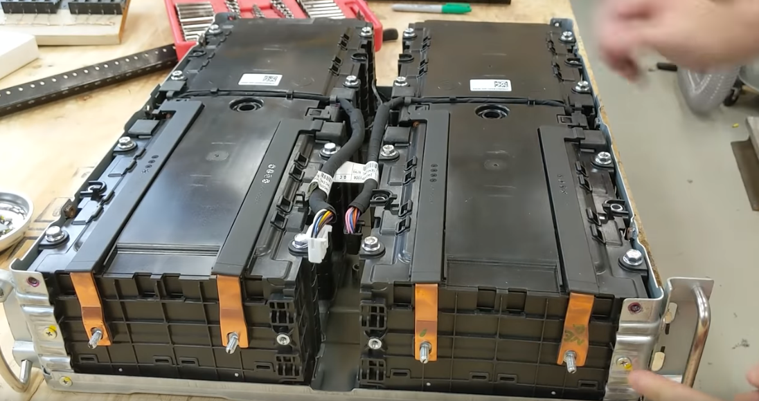
Trying to decide on what I want to do for a battery. Which is impossible for me because every day I do more research on it and every day I think I found exactly what I need, but then the next day I have that same thought again. At first I was sure that I was going to use LiFePO4 cells. Then I was sure I was going to just get a fully assembled pack from amazon or ebay. Today I'm looking at used LG Chem pouches from batteryhookup.

I think they'll be perfect and they're very affordable, and I love that I'll be recycling and reusing. But they're 2/3rd the capacity of new, which will still be enough capacity I think (20s2p = 72v 30ah and 90amp continuous discharge rate (3c) but if 2/3 capacity left, then only 20ah and 60amp continuous discharge rate).

However they would come assembled in 4p blocks which is a problem for two reasons: form factor is too long (22") to fit and 4p is more capacity than I need.

So I would need to be able to split them up, or at least in half into two 2p modules. I would love some advice on how to do that. Here's the page on batteryhookup: https://batteryhookup.com/products/lg-chem-4p-modules-60ah-stackable

I need to decide on what battery tech to use soon because it's driving me crazy. I have like 20 browser tabs open and half of them are endless-sphere.com
 
The more reading I do the more it becomes clear to me that the phrase you get what you pay for applies very well to lithium battery cells. But it is still possible to overpay.
 
JimVonBaden said:
What are your maximum space parameters? This can have a lot to do with what battery you use.

That is a great question!

Here's my latest photoshop mockup:

CA160%20EV%20mockup%204.jpg


The battery box (battery tank?) is designed to resemble a gas tank that has been stretched and distorted to fit the space, but still has that classic teardrop shape.

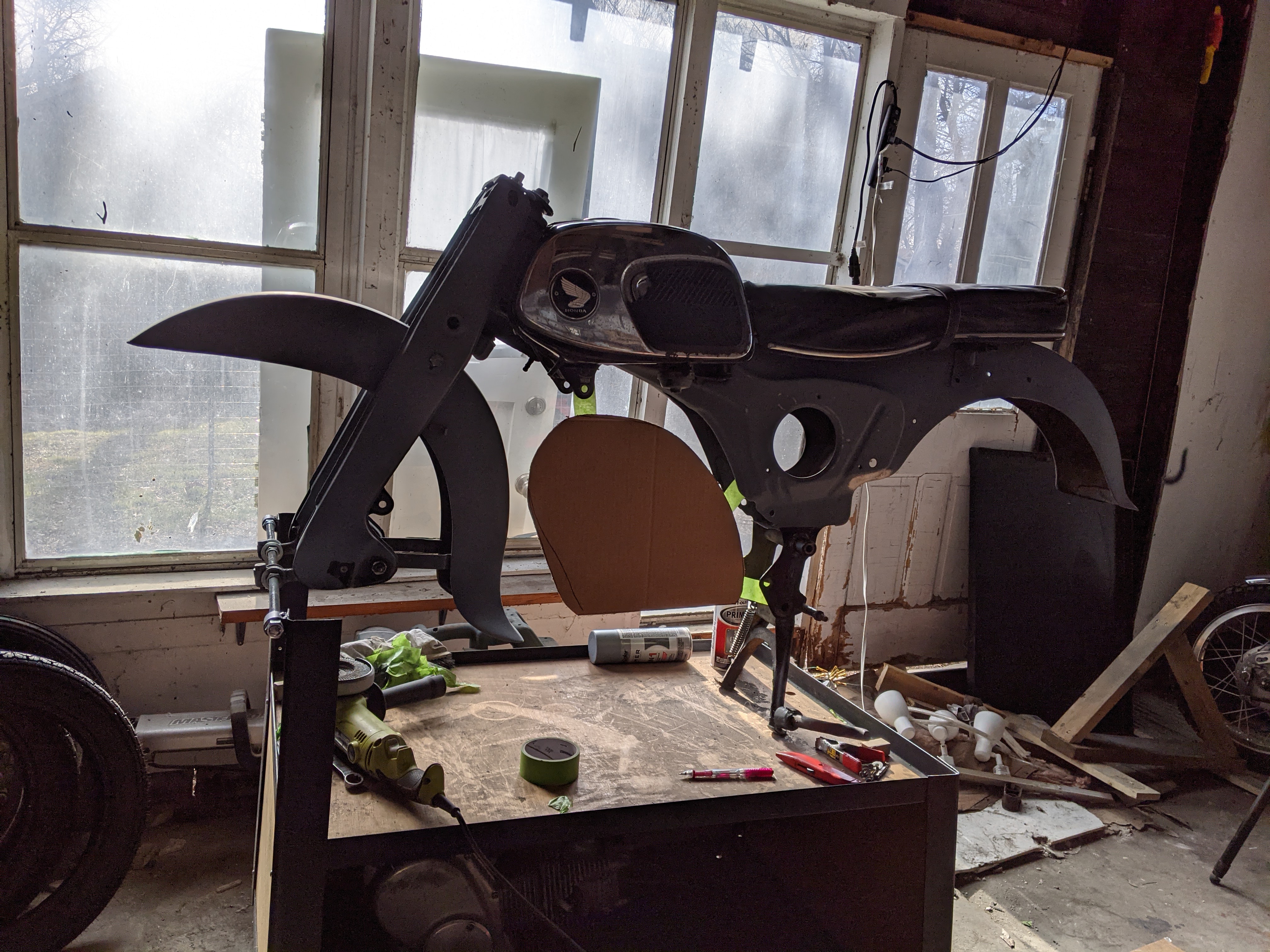
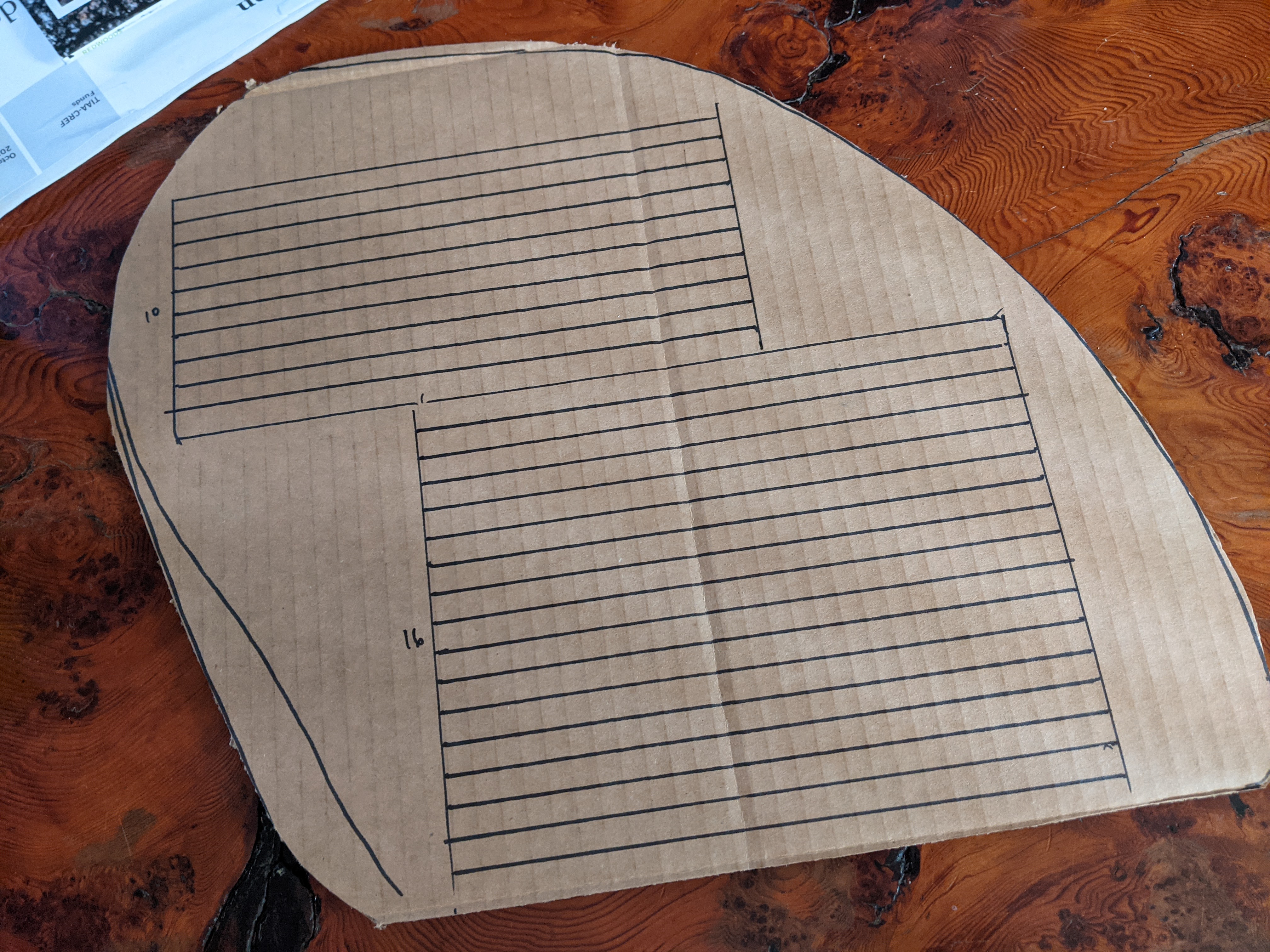
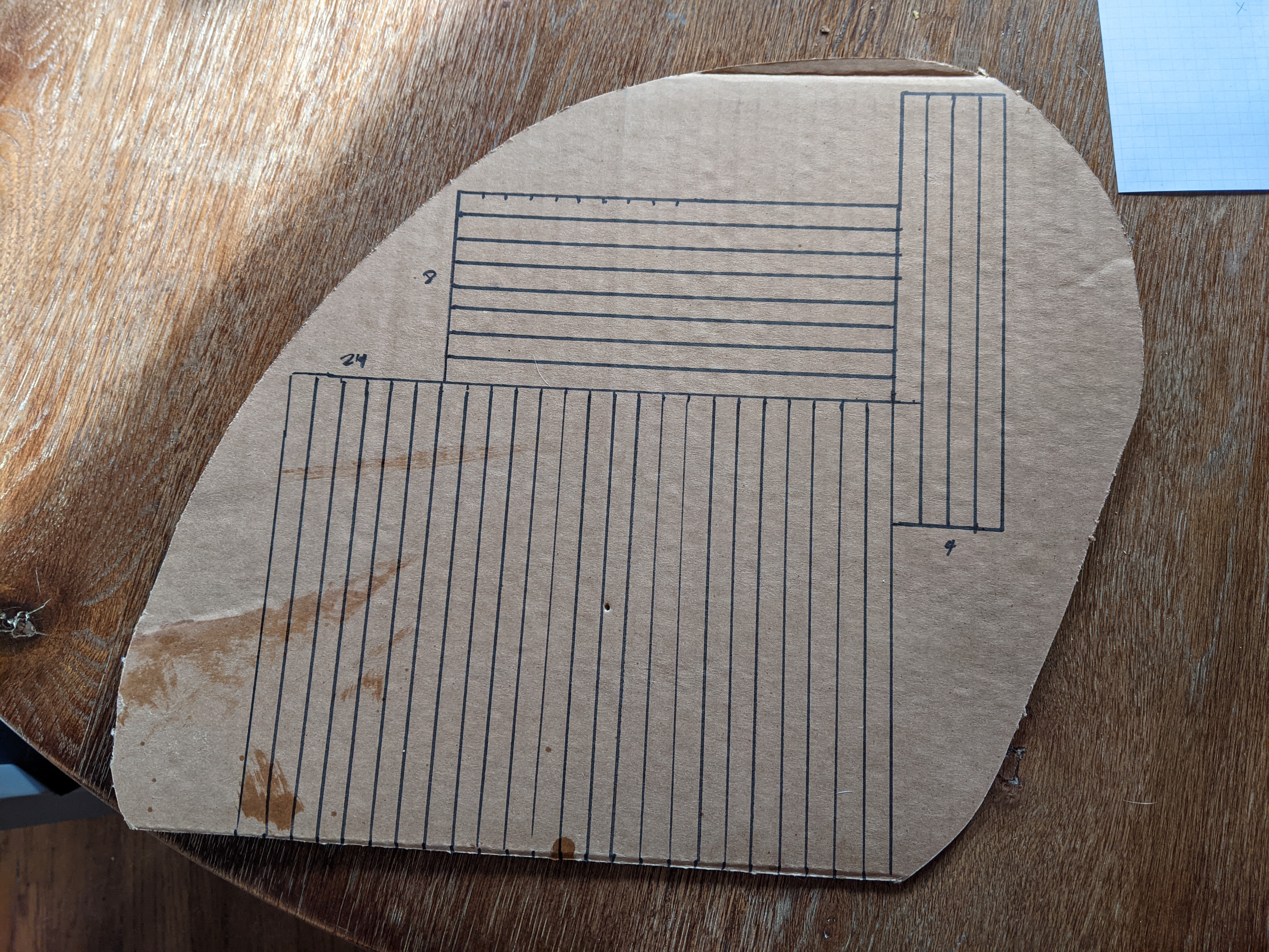
With that in mind, I started doing a little work in CAD (cardboard aided design):

PXL_20210120_185319020.jpg


Now I have a life-size template of the side profile for the battery tank I want to build. But I can make the battery tank as wide as necessary to fit the battery pack.

I'm still liking the used LG pouch cells on batteryhookup.com. Even at 2/3 capacity, if I re-configure them into 20s2p that would get me 20ah and 60amp continuous discharge. Just perfect because my 4kw motor can continuously pull 55amps max.

But they do not list the dimensions and I cannot find that information anywhere online. However for the rack mount units that these modules come out of, they say the dimensions are 22" deep and 17" wide. And they are oriented such that four cells fit in the footprint, so a quarter of that space is 11" x 8" (accounting for the 1" of space between the cells").

Screen%20Shot%202021-01-20%20at%205.29.02%20PM.png


That gives me the footprint of the cells but not the height.

If I'm not mistaken, these are the same cells used in Chevy Volt battery modules. And from https://endless-sphere.com/forums/viewtopic.php?f=14&t=62445 :

The module dimensions are 11" high and 9.5" wide, and a naked pouch is 0.220-inch thick. (5.6mm)

But let's just round up from .22 inches to 10mm. Just to be safe.

So using my conservatively estimated LG pouch cell size of 11" x 8" x 10mm, here's a first try:

PXL_20210120_193105831.jpg


Only 26. I need to get 40 in there! 20s2p configuration.

Assuming it's fine to orient them on their sides, here's another attempt:

PXL_20210120_212455715.jpg


That's 36, but I think I could get 40 into that shape if I adjust here and there. Or if I've overestimated the size of the cells. If not then I can just make the "battery tank" a little bigger - I'll build the battery pack first and then build the tank to fit it. And if all else fails I can cut into the old gas tank and fit some cells in there.

So that's good enough for me.

I just ordered ten 4p modules from batteryhookup.com (plus one extra pack for backup).


I'll need to cut them in half into two 2p modules and wire 20 of them in series, but I think it will be not too hard. The pouches are already welded onto copper and aluminum bus bars, I'll need to cut those pieces in half, along with the plastic. It will be somewhat of an experiment and I haven't seen anybody else do it. Will be fun.

Please let me know if that is a solid assessment, or if I am mixed up about something.

You might be wondering, how will I get the pack in and out of the battery tank? I will build it so that the bottom is a plate that can be unbolted.

For fabricating the tank itself, I plan on using 20ga sheet steel and I'll employ a variety of tools to get it into the compound shape I have in mind. I have a bead roller I will use to start the curvy bend, and I may need to shrink the metal around the top edge. I'll construct it from 4 pieces: the two sides, the top which will be curved but only in one direction, and the bottom which will be totally flat and will probably be something like 16ga or thicker. I'll weld all these together into a tank shape. And then I will either weld on tabs to bold it to the frame, or build a sub frame to cradle it and the sub frame will bolt to the frame.
 
Nice project :) The engine is a stressed member in that frame and they need it, some of the early Honda's would often crack the engine cases at the mounting points from the load. Shouldn't be too hard to allow for in the battery casing design :bigthumb:
 
Did some caclulating to estimate the pack weight:

Batteryhookup.com says that the server rack unit which these 4p modules come out of is 85 pounds, and this youtuber shows it weighing in at 94 pounds on his scale, so let's just meet that in the middle at 90 pounds. And the server rack unit has a total of 56 cells (2 groups of 7s4p packs = 2 x 7 x 4 = 56). 90 pounds / 56 cells = 1.6 pounds per cell. I will have 40 cells so 40 x 1.6 = 64. So my pack could weigh around 64 pounds!

Just to do a little sanity check: I believe these are the same cells used in chevy volt battery packs, and this ebay listing for a chevy volt battery pack containing 32 cells is listed at weighing 49 pounds. 49 pounds / 32 cells = 1.5 pounds per cell. 40 cells x 1.5 pounds/cell = 60 pounds.

FYI I weighed the original gas engine (dry) around 80 pounds.

stan.distortion said:
Nice project :) The engine is a stressed member in that frame and they need it, some of the early Honda's would often crack the engine cases at the mounting points from the load. Shouldn't be too hard to allow for in the battery casing design :bigthumb:

Yes I agree, thanks for making sure I'm aware! It is something I am still thinking about
 
New video! I had a lot of fun making it and I think you will really enjoy it :)

[youtube]G87O15mHBas[/youtube]

Click here if there is an error playing it in the forum's embed video player: https://www.youtube.com/watch?v=G87O15mHBas
 
Back
Top