60degree/120 degree hall sensor spacings

solarbbq2003

10 kW
Joined
Apr 7, 2007
Messages
500
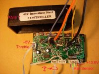
just finished experimenting with hall sensors to change 120degree motor to 60 degree and vice versa. very useful for matching controllers if controller is not easily adjustable between 60/120 degrees
for 60 degree spacing all three hall sensors face in same direction,
for 120 degree the middle hall sensor is facing opposite way.......that simple.
so flipping middle hall sensors around 180degrees ( upside down or back to front however you like to look at it ) is all that needs to be done.
Basically the writing on the hall sensors faces the magnets for 60 degree, the middle sensors side with writing on it faces away from magnets for 120 degrees.
By the way does anyone know how to convert a crystaltye controller from 120degrees ( which is what they run as ) to 60degrees? would mean could be used on alot of different motor types without having to take motor apart.
I know some controllers is just a matter of changing one resistor value to convert, hoping someone might know the secret for crystalyte controllers.
 
Well, if you look at the datasheet for the commutator chip, which is posted here:
http://endless-sphere.com/forums/viewtopic.php?t=764&start=0
on page 1, you won't find any reference to changing the angle. Just a forward/reverse switch. I don't think there's an easy way to do it.

There might be a different commutator chip that could be substituted to provide this function. This would most likely require remapping the pinout. Not really hard, just use a tiny piece of perf board to hold the new chip and run wires to the holes where the old chip was. There should be enough room inside for a "flying board".

A different comm chip might also be able to provide regenerative braking :wink:
 
sorry misread your post, thought you were saying it wasn't that simple to change a motor from 60 to 120. but you were referring to the crystalyte chip, apologies. yes that could be a tricky one.
switching middle sensor around does indeed change from 60 to 120 though.
 
I think it means you could run a Golden Island hub on a Clyte controller, using this hack.
 
it means if you need to match a controller to a motor it is possible, there are two things which you need to match:
1. hall sensor voltage ( 12v or 5v )
2. and hall sensor spacing ( 60 or 120 degree)
You might want to use a particular controller with a particular motor, you could try all the different combinations of wire phases and hall sensors phases to get it running, and find that it will never run correctly if you dont have the 60/120 degree correct and also the correct voltage to run the hall sensors.
Pretty much means that you can run any brushless motor with any controller ( well there are probably ones you cant but talking just with ebike motors)
 
Unfortunately it's not quite that simple. The controller phases go through many cycles during one revolution of the wheel. It's the electrical phase angle that matters to the controller, not the physical rotor angle.

Somewhere there was a diagram comparing the two. I try to find it.
 
The Crystalyte control chip has 3 differential hall inputs, simply swap two of those legs round to flip one hall sensor.
 
really you dont have to actually take out the hall sensor and flip upside down?? I thought one the middle leg was ground, the right leg pos input, and the left leg output when looking at sensor with writing facing you???
You can flip the output and positive wires to get same effect???
boy would that make life easy!!!!!!!!
 
solarbbq2003 said:
really you dont have to actually take out the hall sensor and flip upside down?? I thought one the middle leg was ground, the right leg pos input, and the left leg output when looking at sensor with writing facing you???
You can flip the output and positive wires to get same effect???
boy would that make life easy!!!!!!!!

No, that won't work. You would have to physically flip the sensor over so it responds to the opposite polarity of magnetism. The sensors are typically glued in with epoxy. Some heat and gentle digging will usually get them out in one piece.

What motors use 60 deg spacing?
 
most hub motors i've come across in ebikes of brushless variety seem to be 60degree, crystalyte is a bit unusual being 120 degree, so crystalyte controller only works on 120degree set controllers, trying to run it on another controller wont work usually as most controllers are 60degree.
I'm a bit confused, maxwell metions just flipping the wires on the legs around will reverse, but that would put the the positive wire onto the output of hall sensor?? maybe I dont understand what your saying.
 
I see.
The commutator chip in the Crystallyte controller has differential inputs. By rewiring the signal from the middle hall sensor to the negative input instead of the positive input might work.

I don't have that datasheet on this computer, but you can look at it in the Crystalyte controller sticky thread.
 
Yes, swap the + and - inputs to the chip. I'm not sure if that would really work, but it seems like it should. The comm chip is a surface mounted little bugger and some of the input traces go under the chip, so tracing out where to swap might be tricky. You might be able to just lift the two input legs off the board and bend them up so you can attach tiny wires to them.
 

Attachments

  • commutator chip on board.jpg
    commutator chip on board.jpg
    56.2 KB · Views: 10,960
now this is getting interesting
if its possible to change the crystalyte controllers relatively simply to 60degree it will make possible for alot of motors to be used with crytalyte controllers ( 60degree motors can be change to 120degree by flipping the middle hall sensor in motor around but moding the controller might take less time) , might do some experiments if time permits
 
solarbbq2003 said:
now this is getting interesting
if its possible to change the crystalyte controllers relatively simply to 60degree it will make possible for alot of motors to be used with crytalyte controllers ( 60degree motors can be change to 120degree by flipping the middle hall sensgor in motor around but moding the controller might take less time) , might do some experiments if time permits

Wondering if you have you tried it?

Recently I did an test on my Schwinn AL1020. The spacing of the Hall signals output is 120 deg.

http://endless-sphere.com/forums/viewtopic.php?t=1636

Hy leads Hb by 120 deg.
Hy leads Hg by 240 deg.

If Hg is inverted by an logic IC ( or simple circuit using npn as shown) as H*g.
then Hy leads H*g by 60 deg.

Hence you would have an equivalent 60 deg spacing Hall signal for an 60 deg contoller.

In a similar way, you also invert the 60 deg Hall signal to get an equivalent 120 deg spacing Hall signals.
 

Attachments

  • DSCN7247a.jpg
    DSCN7247a.jpg
    11.5 KB · Views: 10,840
thats a rather good way to do it,
I haven't tried anything as yet with crystalyte controllers,
my understanding is very limited even of what the electrical degree spacing meant, but I was aware that flipping middle sensor upside down did the trick.
Have looked at your results and has certainly helped my understanding of what the degrees refers too. There are off the shelf regen controllers which run off 60degree spacing, sure there would be some people out there would like to try running regen controllers with crystalyte might be one use for changing hall sensor spacing.
 
solarbbq2003 said:
my understanding is very limited even of what the electrical degree spacing meant, but I was aware that flipping middle sensor upside down did the trick.

Flipping senor upside down is equivalent to invert that sensor signal.
Yours is an mechanical way.

Mine is an electrical way.
 
your motor is 120degree so crystalyte controller will work,
could use 5v throttle supply to run halls if they are 5v
might have to mess with how the wires are connected to get to run properly,
36 different combinations possible could just work through all combinations till find the one that works.
 
solarbbq2003 said:
your motor is 120degree so crystalyte controller will work,
could use 5v throttle supply to run halls if they are 5v
might have to mess with how the wires are connected to get to run properly,
36 different combinations possible could just work through all combinations till find the one that works.

The following have to be sorted first:

1) The Hall sensor signal and supply of my stock controler is 5V.
But it seems that Xtyle use 6.8 V for the Hall signal as per Fretcher!
It seems a bit odd because most logics use 5V signal.
Could the stock Hall sensor stand 6.8 V?
If 5 V is used for Hall suppy, will the 5V Hall signal work for Xtyle?

2) The phase-sequence of the stock is Y-B-G.
Xtyle also use the same color code; Y, B and G.
But what is the phase-sequence of Xtlye?

3) Output Vyb leads Hall signal Hy by 60 deg.
What is their phase relationship in Xtyle?

4) Do you know the Hall sensor supply voltage of Golden Controller?
Is it same as Xtyle?
 
1)
You could use the throttle 5v supply from crystalyte controller
but whether or not 5v output will work with crystalyte controller not sure,
I would think would be ok, but that is a guess. If its 6.8v used for throttle halls i dont think a problem to use on motor halls

2)
good question not sure

3)
my understanding of this is not very good, guessing 120deg

4)
crystalyte is unusual using 12v supply for hall sensors, I would think 5v
sorry i'm not more help, I really dont understand much about hall sensor angles etc
 
The7 said:
solarbbq2003 said:
your motor is 120degree so crystalyte controller will work,
could use 5v throttle supply to run halls if they are 5v
might have to mess with how the wires are connected to get to run properly,
36 different combinations possible could just work through all combinations till find the one that works.

The following have to be sorted first:

1) The Hall sensor signal and supply of my stock controler is 5V.
But it seems that Xtyle use 6.8 V for the Hall signal as per Fretcher!
It seems a bit odd because most logics use 5V signal.
Could the stock Hall sensor stand 6.8 V?
If 5 V is used for Hall suppy, will the 5V Hall signal work for Xtyle?

2) The phase-sequence of the stock is Y-B-G.
Xtyle also use the same color code; Y, B and G.
But what is the phase-sequence of Xtlye?

3) Output Vyb leads Hall signal Hy by 60 deg.
What is their phase relationship in Xtyle?

4) Do you know the Hall sensor supply voltage of Golden Controller?
Is it same as Xtyle?

Bought an used Xtyle 48V controller this afternoon. This used controller was tested OK at no-load feeding an 404 motor with 36V and 54V in the shop.
Anyone regonize this Xtyle controller?


Took home and did some bench test without connecting to my motor unit.
Hall sensor supply was measured to be 13.6V.

1)Could the stock Hall senors stand the 13.6V? Don't want to damage the sensors in the motor.

2) If using 5V from throttle supply, could the 5V Hall signal work OK on Xtyle?

Forgot to ask what is the "?" socket for.

Need to do a bit more research and measurement.
 

Attachments

  • DSCN7248 copy.jpg
    DSCN7248 copy.jpg
    48.1 KB · Views: 10,777
Back
Top