Repurposing EScooter Speed Controller and Motor

Joined
Jan 26, 2022
Messages
5
I read through a ton of "speed controller" and related posts, also posts including "Arduino" but couldn't find an answer to my questions, so...

I just took apart an old "Scooter One 2020". There was no battery but otherwise I think it could have been functional. I got it from someone for $10. It was their kid's and it was totally beat up. That's all I know about it. It has a mechanical (cable) rear disk brake.

I'm interested in repurposing the hub motor, e.g. as maybe a robot actuator or drive wheel or a spindle motor or just whatever gadget I make that needs motion.

I am not that familiar with e-scooter controllers although I have some experience with electronics, motors and prototyping in general.

My confusion is to how to repurpose the controller and what some of the wires are for and how to give them signals. I don't want to use the dashboard but instead control the speed controller and motor via either Arduino or Raspberry pi. That said, I will try first to see if I can get the motor to spin with the existing dashboard and throttle.

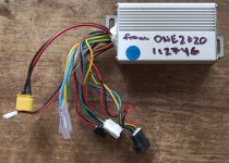
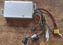
Of the 9 connectors coming out of the speed controller:
- The three phase connectors are clear.
- The hall sensor connector is clear.
- The battery power connector is clear.

What remains are 4 other connectors:

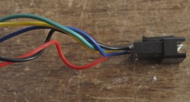
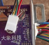
1) one with 4 wires goes to the dashboard.

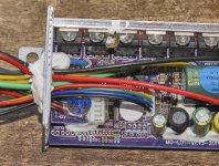
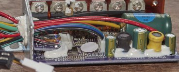
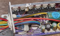
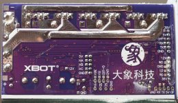
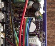
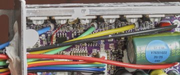
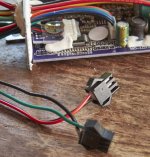
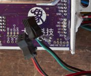
2) two black connectors, both with two wires, both connected on the same mini add-on pcb inside the controller (see pics). No idea what they're for.

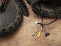
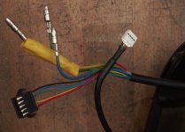
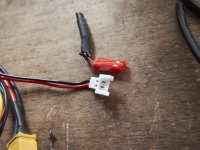
3) one white one with two wires, no idea what it's for and couldn't really tell where it was connected on the PCB unfortunately. But it was connected to a cable going to the back end of the scooter. I wasn't really paying attention while disassembling. I don't think there was a light there but it might have broken off. There was a lot of damage to the scooter.

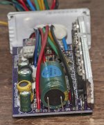
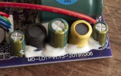
Below are pictures that show the controller in detail. Also one picture of the dashboard.
The controller says "XBOT" on the PCB as well as "MO-LO1-v1.13-20191006" (not sure that's M-zero or M-oh, ditto for LO). I couldn't find any references for ""MO-LO1-v1.13" and variations thereof.
The dashboard PCB is marked "MO-2BLE1-V2.01 20181026".
The black felt marker text on the outside, "ONE2020112746" I wrote for future reference for myself.

I found only a couple of references for the dashboard "MO-2BLE1-V2.01 20181026":
Anyone...iScooter info - ScooterHacking.org
https://rollerplausch.com/threads/midu-flasher-st-link-downgrade-unbrick.5399/page-22
but I suspect it's a commonly cloned one like
https://www.amazon.com.au/Scooter-Clone-Dashboard-Circuit-Replacement/dp/B08F27FDD6 ...although the devil might be in the details between versions of it that are close but not exactly similar.


So my questions are:

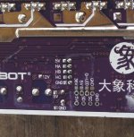
1. How do I communicate with the speed controller using an Arduino or Raspberry Pi? It looks like maybe the wires are connected to the PCB holes labeled 5V, GND, OFF and RX. Some kind of UART? But what speed and what commands? (I think TX is not connected externally).

2. What are the other connectors for?

3. Can I just ignore the other connectors or does the speed controller expect a certain signal from them in order to be enabled?


I know I could run the motor with a generic brushless controller w/ hall inputs and I have some of those on hand but I wouldn't mind using the speed controller that it came with in the scooter if possible.

In some of the pictures below where it's relevant, I put the connectors in the picture next to the pins where they were connected on the PCB.
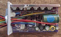
IMG_0250.jpgIMG_0251.jpgIMG_0253.jpgIMG_0256.jpgIMG_0257.jpgIMG_0258.jpgIMG_0259.jpgIMG_0264.jpgIMG_0269.jpgIMG_0270.jpgIMG_0271.jpg


IMG_0274.jpg


This must be for the display (c.f. pic below with front wheel and all the cables coming from the front handlebar tube).
IMG_0275.jpg

These black connectors appear to be connected to the little add-on PCB with the "QC PASS/3" sticker.
IMG_0277.jpg

And that add-on PCB is connected to all or some of these labeled pins underneath: 12V, WD, GND, LD, RD, 36V
IMG_0278.jpgIMG_0279.jpgIMG_0281.jpg

IMG_0282.jpg
The connector to the cable going to the back end of the scooter. The far end of that cable had the red connector, pictured here completely detached because I had to cut it off to pull the cable out of a hole through a metal structure.
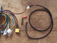
IMG_0285.jpgIMG_0288.jpg
 
You might need to connect the display and measure the voltages on those wires. Most scooters use an analog voltage 1-4v for the throttle input but some use serial data.

There are usually some wires for the brake switches that cut power when the brakes are applied. You can leave those disconnected.

If the controller uses serial data for the throttle it will be challenging to figure out the protocol. You could read the data with the stock display and throttle connected and try to figure it out.

Small controllers that size are very inexpensive these days and you could just buy a new one. Typically you take the pwm output from an Arduino and filter it into an analog signal for a throttle input.
thanks for your reply and input. I think it's serial since the dashboard cable appears to connect to pins RX, OFF, 5V, GND on the speed controller PCB and the throttle on the handlebars only connects to the dashboard. The brake is purely mechanical but maybe that two-wire connector that went somewhere on the rear of the scooter was a brake activation signal... I'm pretty sure you're right that decoding the serial protocol will not be a piece of cake, or it'll be a piece of cake that's been left out in the rain for a week. I really wanted to try to reuse the components I salvaged but it might not be worth that much time investment. I did find something that could be much better which uses FOC and I'm tempted to try that (although I'd need to figure out how to mount the encoder). It is expensive though at ~$35: DRV8302 example. When I tried a hall-based brushless controller on a hoverboard motor it ran really rough until it reached a certain RPM then it was smooth. I suspect FOC control would let me run at near-0 RPM smoothly.
 
Another approach would be to use the display that came with the scooter. The throttle must have a hall sensor somewhere that provides an analog voltage to the display. You could find that and feed your throttle signal at that point.
 
Another approach would be to use the display that came with the scooter. The throttle must have a hall sensor somewhere that provides an analog voltage to the display. You could find that and feed your throttle signal at that point.
I considered that briefly at first but wanted to just use the speed controller. But now that it seems like using the controller is going to be difficult, that might actually be a good solution.

I did take a look at decoding the dashboard-to-speed controller signal though.

I took the dashboard:
IMG_0291 1.jpg

and piggybacked wires onto the pins that connect it to the speed controller down in the base of the escooter.
IMG_0290 1.jpg

Those pins are labelled +, SW, TX, -
I assume TX is transmit, probably serial but I'm not sure.
Not sure what "SW" is.
IMG_0292 1.jpg


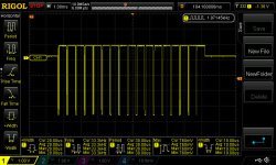
I hooked up an oscilloscope to the TX and SW pins, connecting the probes' ground wires to the "-" pin.
TX is yellow trace.
SW is blue trace.

The TX clearly outputs some kind of digital data. Not sure if the SW is actually doing anything or I just picked up crosstalk from the TX pin somehow since it's signal looks kind of like a dirty version of the TX signal.
If it's serial, I guess that by measuring the width of the shortest pulse I can infer the baud rate? Which would seem to be 115200 baud then.
All of these were taken with the brake and throttle in their neutral/unactuated position.
(I did play with the throttle and brake while looking at the oscilloscope at different time scales but I couldn't really see anything happening, but, I wasn't really sure what to trigger off of, although now in retrospect, I guess I could have tapped into the throttle output, probably a Hall voltage, and triggered off of that rising).

shortest pulse
baud2.jpg

zooming out the timescale, trains of larger nearly-all-the-same pulses demark 3-4 shorter trains of pulses that seem to be encoding data (see next pics)
baud3.jpg

the longer trains of nearly-all-the-same pulses
baud4.jpg


baud5.jpg

the 3-4 transmissions between those longer trains, looks like they are probably encoding data.
baud6.jpg

I think this was the start of the pulse train after the trigger event (triggering on pulse edge downward)
baud7.jpg


Then I connected just the TX and "-" pins to an Arduino Uno. The TX to the RX pin on the Arduino and the "-" to a GND pin on the Arduino.

I ran a program to read from the RX pin while I viewed the serial monitor in the Arduino IDE. The Arduino code had the baud rate set to 115200 (although I did try other speeds without better results).
The result was more or less gibberish (I buffered incoming serial bytes into longer strings before printing to the serial monitor)


11:56:08.720 -> Serial communication started.
11:56:12.559 -> � U � % ` ) *
11:56:12.919 -> p � U � % ` ) *
11:56:13.282 -> p � U � % ` ) *
11:56:13.643 -> � p � U � % ` ) *
11:56:13.971 ->
11:56:14.232 -> ) *
11:56:14.494 -> *
11:56:14.790 ->
11:56:15.084 -> D
� U � % ` ) *
11:56:15.347 -> % ` ) *
11:56:15.609 -> ) *
11:56:15.870 -> ) *
11:56:16.167 ->
11:56:16.425 -> U � ( m
11:56:16.719 -> U � % ` ) *
11:56:16.978 -> % ` ) *
11:56:17.274 ->
11:56:17.534 ->
11:56:17.796 ->
11:56:18.091 -> � U � % ` ) *
11:56:18.386 -> � % ` ) *
11:56:18.647 -> ) *
11:56:18.910 -> ) *
11:56:19.203 ->


I don't know. It's disappointing since I really wanted to re-use the speed controller but at this point I guess I don't want to invest more time in figuring out the data protocol between the dashboard and speed controller given that I can buy a (likely)much more precise FOC motor controller for about $36, https://www.aliexpress.com/item/4000126430773.html
(excluding microcontroller and some kind of encoder)
I did look for any open source attempts to decode this dashboard, which might be a clone of the Xiaomi M365, but didn't find much I could use.
I also looked for other posts of people trying to decode dashboards but the most relevant one I found,
Analysing UART Signal From E-Scooter Controller
wasn't that helpful.
 
Last edited:
SW is typically a switch.
The protocol may actually be gibberish or a digital version of Chinese. It seems to be different for every model of controller.
For $36 it may save you a lot of time and give better results to go with a new controller.
 
Before ordering a controller, have you tested the motor to make sure the halls are all good and there are no phase shorts, etc.?
 
Before ordering a controller, have you tested the motor to make sure the halls are all good and there are no phase shorts, etc.?
Yes, although everything is now disassembled, I reconnected the motor to speed controller, the dashboard hanging out of the free-floating handlebars, hooked up a 36V pack I took from a hoverboard I also just took apart and which thankfully had the same XT60 connector and fired it up. It works perfectly, wheel spins, I see the speed on the dashboard and when I brake the controller sends some kind of command to rapidly stop the wheel from spinning in a fraction of a second (so this scooter had a disk brake plus an software brake).
 
I considered that briefly at first but wanted to just use the speed controller. But now that it seems like using the controller is going to be difficult, that might actually be a good solution.

I did take a look at decoding the dashboard-to-speed controller signal though.

I took the dashboard:
View attachment 354526

and piggybacked wires onto the pins that connect it to the speed controller down in the base of the escooter.
View attachment 354527

Those pins are labelled +, SW, TX, -
I assume TX is transmit, probably serial but I'm not sure.
Not sure what "SW" is.
View attachment 354528


I hooked up an oscilloscope to the TX and SW pins, connecting the probes' ground wires to the "-" pin.
TX is yellow trace.
SW is blue trace.

The TX clearly outputs some kind of digital data. Not sure if the SW is actually doing anything or I just picked up crosstalk from the TX pin somehow since it's signal looks kind of like a dirty version of the TX signal.
If it's serial, I guess that by measuring the width of the shortest pulse I can infer the baud rate? Which would seem to be 115200 baud then.
All of these were taken with the brake and throttle in their neutral/unactuated position.
(I did play with the throttle and brake while looking at the oscilloscope at different time scales but I couldn't really see anything happening, but, I wasn't really sure what to trigger off of, although now in retrospect, I guess I could have tapped into the throttle output, probably a Hall voltage, and triggered off of that rising).

shortest pulse
View attachment 354529

zooming out the timescale, trains of larger nearly-all-the-same pulses demark 3-4 shorter trains of pulses that seem to be encoding data (see next pics)
View attachment 354530

the longer trains of nearly-all-the-same pulses
View attachment 354531


View attachment 354532

the 3-4 transmissions between those longer trains, looks like they are probably encoding data.
View attachment 354533

I think this was the start of the pulse train after the trigger event (triggering on pulse edge downward)
View attachment 354534


Then I connected just the TX and "-" pins to an Arduino Uno. The TX to the RX pin on the Arduino and the "-" to a GND pin on the Arduino.

I ran a program to read from the RX pin while I viewed the serial monitor in the Arduino IDE. The Arduino code had the baud rate set to 115200 (although I did try other speeds without better results).
The result was more or less gibberish (I buffered incoming serial bytes into longer strings before printing to the serial monitor)


11:56:08.720 -> Serial communication started.
11:56:12.559 -> � U � % ` ) *
11:56:12.919 -> p � U � % ` ) *
11:56:13.282 -> p � U � % ` ) *
11:56:13.643 -> � p � U � % ` ) *
11:56:13.971 ->
11:56:14.232 -> ) *
11:56:14.494 -> *
11:56:14.790 ->
11:56:15.084 -> D
� U � % ` ) *
11:56:15.347 -> % ` ) *
11:56:15.609 -> ) *
11:56:15.870 -> ) *
11:56:16.167 ->
11:56:16.425 -> U � ( m
11:56:16.719 -> U � % ` ) *
11:56:16.978 -> % ` ) *
11:56:17.274 ->
11:56:17.534 ->
11:56:17.796 ->
11:56:18.091 -> � U � % ` ) *
11:56:18.386 -> � % ` ) *
11:56:18.647 -> ) *
11:56:18.910 -> ) *
11:56:19.203 ->


No lo sé. Es decepcionante porque realmente quería volver a utilizar el controlador de velocidad, pero en este punto creo que no quiero invertir más tiempo en descubrir el protocolo de datos entre el tablero y el controlador de velocidad, dado que puedo comprar un controlador de motor FOC (probablemente) mucho más preciso por aproximadamente $36, https://www.aliexpress.com/item/4000126430773.html
(excluyendo microcontrolador y algún tipo de codificador)
Busqué algún intento de código abierto para decodificar este tablero, que podría ser un clon del Xiaomi M365, pero no encontré mucho que pudiera usar.
También busqué otras publicaciones de personas que intentaban decodificar paneles, pero la más relevante que encontré,
Análisis de la señal UART del controlador del patinete eléctrico
¿No fue de tanta ayuda?
mil cable amarillo (SW) es el interruptor.
Puedes activar el controlador que en realidad es un xbot, pinchando amarillo con gnd.
 
Back
Top