Cyclomania
10 kW
OkidokiYes that should work
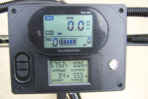
First you need to double-check there is no voltage on the brake sensor connectors. If you can't get the probes in the holes, cut two bits of (ideally non-stranded wire), strip both ends - and poke those into the holes, then you can use the multimeter to check for any voltage.
If you do see a voltage that is 3.3v or 5v (or more!) - stop and post back as that would be unexpected and you can't do what I'm suggesting, you'll likely damage the controller. You'll hopefully see 0v or maybe what's called a floating voltage which would be 1-1.5V probably. If so that's great and you can continue.
Assuming you see 0V-1.5V on the brake sensor connectors - next double check that the black wire on a brake sensor connector has continuity to a black wire on the PAS or throttle connector. It should show continuity - so that means they are all ground as you would expect.
That means the blue wire from the gear sensor needs to be connected to a red wire on the brake sensor (i.e. not ground)
And that means only one red wire correct? On one of those brake sensors. Both brake sensors have two wires( meaning four in total). I need to connect it to one of those four. Namely a red one from one of them, to be clear, correct?
") When I hooked the battery onto the bike and checked one red from the brake sensor and one black from the brake sensor I could see the voltage sometimes shooting above four
When I hooked the battery onto the bike and checked one red from the brake sensor and one black from the brake sensor I could see the voltage sometimes shooting above four