Lishui "Open Source Firmware" project / KingMeter 5S

You can check, what the display sends with the USB UART converter with your laptop first.
Hi, I did as you suggested and at the beginning controller Tx was silent, display kept sending "00 E0 00 00 E0 00 00 00 E0 E0 00 00 E0 00 00 00 00 E0 00 00 E0 E0 00 00 E0 00"
After a bit of fiddling with wires controller Tx started emitting what is pasted below. So I hope this is wires connection issue - I used some isopropylic alkohol to Rinse Tx/Rx plug and so far E30 is gone
1740258200384.png

I tested it with motor connected using WALK function and motor seems to start, however sometimes (f.i. starting with wheel not lifted from the ground I could hear it rotating but wheel stood still. @stancecoke is it possible that in some conditions motor starts backwards? I am trying to figure out if it is faulty sprag or something in FW :) It was a bit difficult to test further because of temperature and "spider web" setup :D

Just as I wrote this post, E30 appeared :\
 
Last edited:
display kept sending
Please switch to 9600 BAUD, otherwise, you read nonsense.
The motor can only start correctly, if you accelerate the wheel by pedaling first, so the motor start without load in the freewheel. If the wheel is blocked, it might happen, that the motor starts backwards.
 
Hmm... When voltage on my bench supply is set to 48.6V every power on ends with E30, I decreased voltage to 47.6V and I had maybe one E30 in 10 power ups, I decreased by 1 more volt and I am playing around and it looks like1 in 20 ends with E30, 54.6V also seems to be quite successful, around 50.6V is again problematic. What kind of sorcerry is that??! PSU ripples? But suprisingly it seems to be affecting initialization phase - once this "handshake" is done, I can adjust voltage to this 48V and it seems to be ok. I have Riden 60V 30A step down unit working with 1500W PSU that is sold together. I will charge battery to ~ 49V and check how it behaves then powered from battery :)

Edit: Battery charged to 48.2V and also E30 on power up :D
 
Last edited:
Hmm... When voltage on my bench supply is set to 48.6V every power on ends with E30, I decreased voltage to 47.6V and I had maybe one E30 in 10 power ups, I decreased by 1 more volt and I am playing around and it looks like1 in 20 ends with E30, 54.6V also seems to be quite successful, around 50.6V is again problematic. What kind of sorcerry is that??! PSU ripples? But suprisingly it seems to be affecting initialization phase - once this "handshake" is done, I can adjust voltage to this 48V and it seems to be ok. I have Riden 60V 30A step down unit working with 1500W PSU that is sold together. I will charge battery to ~ 49V and check how it behaves then powered from battery :)

Edit: Battery charged to 48.2V and also E30 on power up :D
Maybe there is some logic in the display which causes it to want a different response for different voltages.

If you expect the voltage effects the UART lines, measure the voltage with a scope on the UART lines and see if there is a difference when changing voltages. I doubt it is the problem but who knows. Usually ttl uart is clamped to either 3.3v or 5v the display I have uses 5v, I haven't checked the controller but expect the same.
 
But bear in mind that for master branch I do not experience similiar dependencies and everything is working smoothly regardless of voltage and this makes me think that it is some software related. I used chatgpt to compare display communication methods for master and sensorless branch and it returned lack of autodetect function and lack of FirstRunFlag. Do you think it might be the culprit?
 
As written before, there will be some condition that lets the code jump to the error handler, where the program will run in an infinite loop.
But from the distance it is not possible to debug that.

https://github.com/EBiCS/EBiCS_Firm...21d52dbe661d53a394d5e81c589d/Src/main.c#L1442

You can comment out the while loop for testing, but it is not recommended, as the error handler protects the hardware, if something wents wrong.

You can log the startup messages from the display and the answers from the controller also and compare, what is different when the display ends in E30. @9600 BAUD ;)

regards
stancecoke
 
Last edited:
Here are outputs from logic analyser. D0 is controller Tx, D1 is controller Rx. What comes from the display looks to be the same in case of E30 and normal operation. Tx of the controller changes state from low to high during transmission of the first frame from the display. I guess I have to use a debug in eclipse, right?

Power up at 44.6V, succesful operation:
1740310706503.png

Zoomed to first pair of display message and controller response (15 and 13 bytes).
Tx: 0x3A·0x1A·0x53·0x05·0x00·0x00·0x0D·0x14·0x00·0x93·0x00·0x0D·0x0A
Rx: 0x3A·0x1A·0x53·0x07·0x02·0x40·0x1E·0x9E·0xE8·0x20·0xD4·0x4E·0x03·0x0D·0x0A
1740311004023.png

zoomed to part here frames from display become 10 bytes.
Tx: 0x3A·0x1A·0x52·0x05·0x00·0x00·0xFA·0x00·0x00·0x6B·0x01·0x0D·0x0A
Rx: 0x3A·0x1A·0x52·0x02·0x33·0x00·0xA1·0x00·0x0D·0x0A

1740310931360.png


Power up at 48.6V which ends in e30 error:

1740311116359.png


Zoomed to first 15 bytes frame from the display:
Tx: -
Rx: 0x3A·0x1A·0x53·0x07·0x02·0x40·0x1E·0x9E·0xE8·0x20·0xD4·0x4E·0x03·0x0D·0x0A

1740311189576.png


Zoomed to first 10 bytes frame fro the display:
Tx: -
Rx: 0x3A·0x1A·0x52·0x02·0x33·0x00·0xA1·0x00·0x0D·0x0A
1740311258174.png
 

Attachments

  • 1740310806108.png
    1740310806108.png
    26.3 KB · Views: 1
Last edited:
This confirms the suspicion that the program jumps to the error handler. You should use a Workbench debug session to prove that.

I remember, that there were issues with the interrupt priorities, that can cause this behaviour. I guess, in the sensorless branch, all interrupts have the same priority (all set to highest :) ). In the master, different interrupts have different priority.
The priority definitions are spread a little all over the code. Some are in the main.c and many are in the msp.c file. So you will have to search a little... Keyword HAL_NVIC_SetPriority

https://github.com/EBiCS/EBiCS_Firm...ceabb98f8360a747d/Src/stm32f1xx_hal_msp.c#L65

It would be realy nice when you cloud review an maybe accept it.
Thank you for your efforts. I had no closer look at your changes, the main thing seems to be the averaging the torque, that you switched from >>5 to /PAS_IMP_PER_TURN

If you do so, please remind, that a division takes a lot of clock cycles, so avoid it, where you can. That's the reason, why I use a right shift instead, where ever possible.
Code:
(uint32_torque_cumulated/PAS_IMP_PER_TURN)/uint32_PAS

uint32_torque_cumulated/(PAS_IMP_PER_TURN*uint32_PAS)

Be aware, that my way of averaging is not the arithmetic middle of the values of one crank revolution anyway. See this little piece of code, just hit the run button at the top of the window. The value iterates to the final value much slower.

regards
stancecoke
 
Last edited:
Doesn't that just mimic a sliding window kernel with very large base that way? While only using one memory location but losing finetuning of weights.
 
losing finetuning of weights.
I've experimented a lot with different algorithms for averaging and found it sufficient this way. It's quite tricky to find a good balance between a smooth and pulse less assistance and a fast response to changes in the riders effort.
But of course you can try your own ideas, that's what open source development is made for ;)

regards
stancecoke
 
But of course you can try your own ideas, that's what open source development is made for ;)
It's probably fine :) I was just wondering if the effect was similar or not.
I will have a look at all timings to see if something can be improved by eliminating expensive operations but you seem to have already done a fine job already.
Enabeling lto might give some improvement though, especially on code size. I rebuild my build with lto enabled and now it fits into 32k again. Inlining some functions will also avoid expensive context switches especially in ISRs which might give some improvement at code size cost.
 
Last edited:
Thank you for your efforts. I had no closer look at your changes, the main thing seems to be the averaging the torque, that you switched from >>5 to /PAS_IMP_PER_TURN

If you do so, please remind, that a division takes a lot of clock cycles, so avoid it, where you can. That's the reason, why I use a right shift instead, where ever possible.
I was not aware of the division problem.
I changed it to a multiplication using the Fast Integer Division Approximation (chat gbt gave me this hint)
Now it still have the same functionality but without division in the main loop.

I have make a new pull request.

Unfortunaly i could not test if it compile well because of a Githup update the online compiler with the Github-Action don`t work any more. It would be nice if you can have a look on this.

Beside this i have only done changes to the Java Configurator

Be aware, that my way of averaging is not the arithmetic middle of the values of one crank revolution anyway. See this little piece of code, just hit the run button at the top of the window. The value iterates to the final value much slower.
Of this fact i was aware. It was the main reason for my improvements regarding the impulses per turn.
I have a sensor with 16 Impulses per turn (Erider T17) and when you press with e.g. 100% torque it need 4 turns to reach even 80% of the aimed torque output.
That was for me much to slow especialy when starting on a hill.


During writing the documentation there come up some questions to me.
Is the gear ration value somehow needed when you have a external speed sensor?

You have recommended me a maximum motor current of 50A for my Shengyi DGWX2 Motor (gear motor 250 W) and say my maximum Battery Current of 10 A would be a good value for my controller.
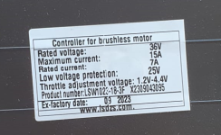
Controller_Typenschild.PNG
How you came to this conclusions ?
I think the maximum Battery Current protect mainly the controller against overheating and the battery against to much load.
At the end the controller protected it selfe by measuring the temperature but a good value prevent that it even come to overtemperature.

But i don`t get the point with the phase curent (motor current). How can it even be higher then the battery current because there are not so big condensators in the controller that it can output a higher current the inputed by the battery i think.
Or in other words what could happen in worst case if sombody enter a much higher value (as long as the motor is not a way to small for the controller and the maximum Battery Current is set properply )?
 
Fast Integer Division Approximation
I that what we are calling fixed point arithmetic these days?
I would not be too bothered by it as you save around 3-5 cycles and probably less. It is reordered and pipelined anyway unless you compile with very low optimization settings. If it was in a big loop sure, but otherwise I would not bother too much with it and focus elsewhere (cough cough Knuth, cough premature optimization). Better to avoid division if you can but a single one will not matter too much. But that's my opinion and it's not my repo :).

At the end the controller protected it selfe by measuring the temperature
There is no temperature sensing on the FETs, only the MCU. Which is a bad representative of the FET temperature at best (I got my fets up to about 90c and the MCU was 25c pretty much doing nothing). If you have a temperature sensor on the motor windings it's better since you know if the motor is cooking the FETs will also be nice and crispy. (pwm was stuck on, drawing 5A DC continously)

How can it even be higher then the battery current because there are not so big condensators in the controller that it can output a higher current the inputed by the battery i think.
I'm not too familiar with the electrical characteristics of this situation but my guess would be the giant inductor has something to do with it as well.
 
Last edited:
How can it even be higher then the battery current because there are not so big condensators in the controller that it can output a higher current the inputed by the battery i think
Screenshot-2020-06-05-at-11.19.32-1024x656.png

The servo drive behaves as a step-down DC/DC converter. Ignoring the inefficiencies and commutation details the product of “input voltage * input current” should be equal to the product of “output current * effective motor voltage”.
Source

In short:
Code:
battery current = duty cycle * motor current

;)

Unfortunaly i could not test if it compile well because of a Githup update the online compiler with the Github-Action don`t work any more. It would be nice if you can have a look on this.
I fixed that!
1740660710401.png
 
Last edited:
I added some more opcodes for the bafang tft displays like the brake signal and some error reporting. Pull request should compile and run, but I cannot test it on windows (compiles fine on linux with arm toolchain). If someone with a 850/860 display can confirm it's not just mine which runs at both 9k6 and 1k2 baud that would be nice. My display starts in 9k6, transmits two requests and then does the same at 1k2 until it gets a response.
Some opcodes report on the "information" screen in settings like Calories (No idea what it normally is for) and Range. They now report the motor temperature and the actual voltage in mV.
 
Sure, but I'm not in a position to guarantee anything, mainly maintaining my sanity atm (recovering from a burnout) by reverse engineering things (also working on custom code for the lcd8h kunteng display I have which I broke the plastic from since it's definitely not ABS as it deteriorates in the sun). My handle here and on github are the same.

Now working on the weird system bafang has in place for the motors/wheel diameter/speed limit setting.

The value is dependent on the wheel size (which cannot be send to the motor from the display afaik. It can only programmed with the programmer and PC tools, but you can change the wheel size on the display but the only thing that will do is both alter speed setting on the display (the rpm -> kph or mph conversion) and will also change the speed limit setting (0x16 with opcode 0x1F).
Setting the wheel size to 100cm gets you the speed limit in equivalence to meters/minute (416) at 25kph limit. Setting it to 200cm (that's a big wheel!) gets you half of it (208). So my guess is the wheel size is assumed hardcoded in the bafang motors, otherwise it would not make sense since you'd be working with two variables (wheel size and speed limit).
The current code, and every example of anybody decoding the bafang uart protocol on github, assumes it to be wheel size but it lowers with increased size. And in every codebase it is commented out or ignored :unsure:

Two minutes later and I guess now it's: (rpm * wheeldiameter (in cm)) = cm/min. With wheel diameter being an unknown and not send to the controller from the display afaik.

update: this works as expected. Speed/limit is quite accurate on the bafang displays.
 
Last edited:
I have make a new pull request.
I have merged your pull request, but I have not tested it. I hope it works ;)

Pull request should compile and run
I have not merged your pullrequest, as you have new #defines in the config.h, that the Java tool will not create.
I don't know how many users really use the Java tool, but I don't want newbies despair, if it doesn't work, like described in the Wiki.

@TENET: perhaps you can update the Java Tool with the new display definitions of @consp. And perhaps with the few parameters, that I put into the main.h to keep the Java Tool working, also. ;)
There is an issue reported on github, perhaps you can try the recommented solution, if you are editing the Java Tool anyway.


regards
stancecoke
 
Last edited:
I'll have a look if I can find my java skills somewhere, should not be too hard to add.

edit: Done. Also added issue #54 fix in there.
I'll edit the wiki as well if this is sufficient. Also done in anticipation of pull request acceptance :). Image needs updating though.
 
Last edited:
edit: Done.
Hm, I tried your latest commit, but there still is just one Bafang option in the configurator and compiling throws an error with display set to Bafang.
I think, you have not updated the executable .jar file in the main folder?!
../Src/display_bafang.c:183:17: error: a label can only be part of a statement and a declaration is not a statement
uint16_t batval = ((uint32_t)(MS->Voltage*CAL_BAT_V)/100) & 0x0000FFFF;
^~~~~~~~
Src/subdir.mk:54: recipe for target 'Src/display_bafang.o' failed
make: *** [Src/display_bafang.o] Error 1
1740914799737.png
 
Last edited:
I think, you have not updated the executable .jar file in the main folder?!
Ah, forgot that one ... generally try to avoid putting artifacts in repositories so completely forgot to add it. 🤦‍♂️

../Src/display_bafang.c:183:17: error: a label can only be part of a statement and a declaration is not a statement
uint16_t batval = ((uint32_t)(MS->Voltage*CAL_BAT_V)/100) & 0x0000FFFF;
^~~~~~~~
Src/subdir.mk:54: recipe for target 'Src/display_bafang.o' failed
make: *** [Src/display_bafang.o] Error 1
Will fix this. It's a ANSI-c quirk which on some compilers drains into C99/C11 or whichever they use as defaults. Declarations not being allowed inside switch/case while they should be (and treated as registers). There is a dirty fix (;; after a label, or creating code blocks) but I'll do it like it should have been done in the old days. This is also the reason for forcing 32bit behaviour as there is no guarantee the compiler will use 32bit arithmetic when you do not force it (depending on C standard used), almost all do but I've been hurt before.

I'm pretty sure this is due to my compiler setup, which allows this kind of statements and unfortunately almost unavoidable if you deal with multiple compiler versions on multiple platforms. It's good to have multiple people test things that way. Which one did you use?
 
Last edited:
That would explain the difference, I'm using gcc 12. The GCC you are using defaults to C99, 11+ to C17. If it works no reason to change unless you run into a compiler bug. I've pushed the changes to the branch.
 
I've pushed the changes to the branch.

Hm, now the next error appears, if I select one of the Bafang displays :(

Code:
../Src/main.c:246:1: error: unknown type name 'No2_t'; did you mean 'fpos_t'?
 No2_t No2;

and in the basic settings.ini file seems to be something wrong, as the default path definitions are not correct.
1740926247962.png

it should be:

1740926315603.png
 
Last edited:
Interesting, I'll install the STM workbench on my windows machine since there seem to be a bit more differences than I expected.
 
Back
Top