Throttle blew up - need advice installing new similar one (with photos)

tazarp

100 µW
Joined
Oct 23, 2024
Messages
7
Location
United Kingdom
Hey there,
I'm looking for some advice from you guys. I've tried to make the issue as clear as possible along with photos. I'm a complete amateur and this is my first time doing this. Your help is really appreciated!
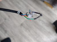
  • Old half-twist throttle with ignition key blew (pop + smoke).
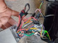
  • It connects into a big cable bundle at the handlebar (includes lights, horn, brakes, etc.).
  • That bundle runs all the way down to the controller.
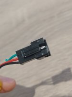
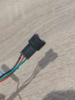
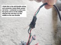
  • New throttle/ignition has the same coloured wires (red/black/green + blue + yellow), but in a different order than my old throttle/ignition.
  • I was going to cut the old wire near the handlebar and splice the new one into it.
  • I think connecting the new throttle to the existing wiring at the top would be much cleaner.
  • BUT before I start cutting and soldering, I want to test the new throttle by plugging it in down at the controller first, just to make sure everything works.
  • There's always a chance the old wiring or the controller could be bad because of the way the old throttle blew.
  • The throttle blew because I had an issue with the battery connectors that I didn’t realise at the time. It caused an error code on the display, and the throttle stopped working. I kept turning the ignition on and off trying to fix it, and eventually the throttle popped and smoked.
Two questions:
  1. If you were in my position, how would you personally install this new throttle setup?
  2. How do I safely rearrange the red/black/green wires on the black connector down at the controller? I'm a complete amateur at this stuff and have never removed or moved pins before. Any tips would really help!
Thanks so much!
 

Attachments

  • ebike-1.jpg
    ebike-1.jpg
    404.7 KB · Views: 16
  • ebike-product-page.jpg
    ebike-product-page.jpg
    299.8 KB · Views: 15
  • ebike-6.jpg
    ebike-6.jpg
    2.5 MB · Views: 16
  • ebike-5.jpg
    ebike-5.jpg
    377.4 KB · Views: 16
  • ebike-4.jpg
    ebike-4.jpg
    278.2 KB · Views: 17
  • ebike-3.jpg
    ebike-3.jpg
    445.5 KB · Views: 15
  • ebike-2.jpg
    ebike-2.jpg
    388 KB · Views: 17
Those thick wires in the third pic are phases for the motor. You don't want to touch those, nor should you "go by color" on generic parts like this.
Multimeter + that last pic should be enough, but someone who knows those controllers will hopefully come and tell what to connect and where.
 
You don't see too many ebikes that use the molded connectors on the handlebars and discrete JST plugs at the controller. You say the bike has a display and you show a push button throttle combo. That round 5 pin connector in the first picture goes to the throttle unit then? Does the display have a power on button too?

Well, there should be a 5 pin plug coming from your throttle. I believe three wires will be the +5V power, signal, and ground for the throttle. The two remaining wires go to the throttle switch. One is battery and the other is a controller input that starts the controller when it gets battery power.

If it were me, I'd map the continuity from that connector to the plugs on the end of that handlebar harness. You need to find the connector for the two remaining wires. That's going to carry battery voltage, They may not be blue and yellow from the controller.

By the way, is all of this factory wiring or did someone do some custom wiring?
 
Also, it could very well be that it is not only the throttle that broke, but the entire controller: ‘pop and smoke’ sounds like the battery voltage wire (which goes to the ignition key) shorted to something else, i.e. ground or worse: To the throttle supply voltage (4,2 V) and/or to the throttle input of the controller. Both can not handle battery level voltage and that part of the contrller would then be destroyed. Just fyi.
 
I agree with the above. If something went pop, the battery wire to the throttle switch must have shorted on something, which would almost certainly do consequential damage, so don't be surprised if it still doesn't work after you sort out the throttle. If you can identify exactly which wires shorted (should have burn marks), we would be able to explain the consequences.

There is a connector on your controller for the ignition switch. It'll have two wires, one of which will have live battery voltage. The other would be typically red, pink, orange or brown, but anything is possible except black, which is always ground. Those to wires have to be bridged for the controller to work, either by a bridge or the switch in the throttle that isn't really needed if you have an LCD/LED control panel with it's own switch.
 
How do I safely rearrange the red/black/green wires on the black connector down at the controller? I'm a complete amateur at this stuff and have never removed or moved pins before.
You can remove the male pins from the connector to reorder, then reinsert them in the housing. The pins have a little hook that keeps them in place, that you can depress with a paperclip in order to pull them out.
 
You don't see too many ebikes that use the molded connectors on the handlebars and discrete JST plugs at the controller. You say the bike has a display and you show a push button throttle combo. That round 5 pin connector in the first picture goes to the throttle unit then? Does the display have a power on button too?

Well, there should be a 5 pin plug coming from your throttle. I believe three wires will be the +5V power, signal, and ground for the throttle. The two remaining wires go to the throttle switch. One is battery and the other is a controller input that starts the controller when it gets battery power.

If it were me, I'd map the continuity from that connector to the plugs on the end of that handlebar harness. You need to find the connector for the two remaining wires. That's going to carry battery voltage, They may not be blue and yellow from the controller.

By the way, is all of this factory wiring or did someone do some custom wiring?
Thanks for the help!

This is a pre-built ebike — all factory wiring. It's one of those fat-tired folding models.

Regarding the molded connectors on the handlebars, I did some research, and it looks like it's similar to a "Bafang 1T4" (or just "1T4") cable. The only ones I found online have four colored connectors, whereas mine has five.

The bike uses a smaller "EN06" display with its own power button. When the bike was working:
  • If I turned on the display while the ignition was off (by holding the button), it would show a low battery warning and shut down within a few minutes, which I believe is normal since the ignition cuts battery power.

  • With the ignition on, the display would show the correct battery level.

Right now, I can’t power up the display at all, probably because the ignition has been off for a while. I just need to get the ignition working again to check if everything else is still functional.


There was a green 5-pin connector coming from the original throttle, which plugged into the loose green connector near the handlebars (shown in the photos). I've disconnected it now since the throttle was no longer working, and I was planning to splice the new throttle wiring into that same 5-pin harness. You can see the disconnected cable in photo 6, towards the bottom left and i've also attached more photos of it.


The bike didn't originally have issues because of the throttle/ignition. I think it started with the battery.
It uses one of those "silverfish" style batteries that slide down under the seat. I didn’t realize at the time that the connectors were slightly misaligned and some were even bent, which probably prevented a good connection.
I had a bad fall on the bike, which might have caused the battery issue (forcing it down might have caused the connectors to bend too), and while the throttle worked right after, it stopped working the next day.


I've managed to fix the battery connectors now, so I'm just trying to get the throttle/ignition sorted to see if everything runs smoothly once the ignition is switched on. I want to plug the new throttle/ignition in directly at the bottom of the controller. I just don't know which wires goes where.
 

Attachments

  • IMG_20250427_184110253.jpg
    IMG_20250427_184110253.jpg
    1.6 MB · Views: 4
  • old-cable.jpg
    old-cable.jpg
    7.3 MB · Views: 5
  • en06 display.jpg
    en06 display.jpg
    1.5 MB · Views: 5
  • another photo of controller wires.jpg
    another photo of controller wires.jpg
    2 MB · Views: 4
  • another photo of controller wires 3.jpg
    another photo of controller wires 3.jpg
    960.9 KB · Views: 4
  • another photo of controller wires 2.jpg
    another photo of controller wires 2.jpg
    1.1 MB · Views: 5
  • my bike.png
    my bike.png
    831.6 KB · Views: 5
  • IMG_20250427_184058527.jpg
    IMG_20250427_184058527.jpg
    1.7 MB · Views: 5
Also, it could very well be that it is not only the throttle that broke, but the entire controller: ‘pop and smoke’ sounds like the battery voltage wire (which goes to the ignition key) shorted to something else, i.e. ground or worse: To the throttle supply voltage (4,2 V) and/or to the throttle input of the controller. Both can not handle battery level voltage and that part of the contrller would then be destroyed. Just fyi.
Hey, thanks for your help. I'm really hoping the controller hasn't been affected. I remember when I was turning the key quite frantically, trying to get the display to turn back on. The ignition had become loose, so it was often turning around as I turned the key, which made it harder to click into the on/off position, but it did eventually. From what I remember, the whole ignition turned, and then it popped. I think it might have turned too much and pulled one of the little colored wires out of the ignition or something.
 
I agree with the above. If something went pop, the battery wire to the throttle switch must have shorted on something, which would almost certainly do consequential damage, so don't be surprised if it still doesn't work after you sort out the throttle. If you can identify exactly which wires shorted (should have burn marks), we would be able to explain the consequences.

There is a connector on your controller for the ignition switch. It'll have two wires, one of which will have live battery voltage. The other would be typically red, pink, orange or brown, but anything is possible except black, which is always ground. Those to wires have to be bridged for the controller to work, either by a bridge or the switch in the throttle that isn't really needed if you have an LCD/LED control panel with it's own switch.
Thanks for helping! I've inspected the wires and can't seem to find any burn marks. Is there any chance you can provide me with a picture of the ignition switch wiring or point it out on my photos?
 
It makes no engineering sense to use a throttle with voltage indicator built in. A normal three wire throttle has only 5V, GND, and signal, so full battery voltage can't get in there and cause nonsense. You can put a voltmeter elsewhere on the handlebars or battery, but putting it in the throttle is a stupid thing to do.

In places that deal with lots of rain, folks have found that 48 volts (or whatever battery voltage) can become bridged with water to the signal wire, and even with low conductivity can cause the throttle to fail wide open. No thanks.

Making one part that does two different necessary things is good engineering, but stuffing two unrelated parts that are at odds with each other into a single component is incompetent engineering.
 
You can remove the male pins from the connector to reorder, then reinsert them in the housing. The pins have a little hook that keeps them in place, that you can depress with a paperclip in order to pull them out.
Thanks for the reply and video. I just tried what he did in the video but I couldn't get them out. I'll look into it more. If I can't manage to plug the new throttle straight into the controller at the bottom of the bike, then the best thing to do might be to just connect the coloured wiring from the new throttle/ignition to either the old green 5-pin connector cable (that has the same coloured wires).
 

Attachments

  • old-cable.jpg
    old-cable.jpg
    7.3 MB · Views: 4
  • IMG_20250427_200000820.jpg
    IMG_20250427_200000820.jpg
    662 KB · Views: 3
  • IMG_20250427_200007005.jpg
    IMG_20250427_200007005.jpg
    596.7 KB · Views: 3
  • IMG_20250427_200013409.jpg
    IMG_20250427_200013409.jpg
    803.7 KB · Views: 3
  • IMG_20250427_200016314.jpg
    IMG_20250427_200016314.jpg
    764.9 KB · Views: 3
I've just found this... it's not ideal because I want a half-twist throttle, but this particular one seems like your standard generic type and has the same green 5-pin male connector. It's just a throttle and ignition with no extra voltage indicator, just like my old one. It will be shipped from China, but it shouldn't take long to arrive. Even though it's not ideal because it's not a twist throttle, I could buy it, plug it in directly, and see if the ignition turns the controller on. Then afterwards I can think about how to install the new half-twist throttle I have. Well I say afterwards.. i'll still try now so your help is much appreciated!
 

Attachments

  • main-image-7.jpeg
    main-image-7.jpeg
    75.4 KB · Views: 2
  • main-image-1.jpeg
    main-image-1.jpeg
    59.7 KB · Views: 3
  • main-image-3.jpeg
    main-image-3.jpeg
    99.7 KB · Views: 3
  • main-image-6.jpeg
    main-image-6.jpeg
    44.2 KB · Views: 3
It makes no engineering sense to use a throttle with voltage indicator built in. A normal three wire throttle has only 5V, GND, and signal, so full battery voltage can't get in there and cause nonsense. You can put a voltmeter elsewhere on the handlebars or battery, but putting it in the throttle is a stupid thing to do.

In places that deal with lots of rain, folks have found that 48 volts (or whatever battery voltage) can become bridged with water to the signal wire, and even with low conductivity can cause the throttle to fail wide open. No thanks.

Making one part that does two different necessary things is good engineering, but stuffing two unrelated parts that are at odds with each other into a single component is incompetent engineering.
Hi there thanks for replying. I see where you're coming from! My old throttle didn't have a voltage indicator built in. I've looked everywhere to find my same old throttle without it, but i've had no luck at all. I think having the voltage indicator can make it look more appealing to potential thieves too when riding out because of the LED light. Having one is something i'm not really bothered about.

Do you have any idea where the blue and yellow wires on my new throttle/ignition connect to the controller?
 

Attachments

  • ebike-product-page.jpg
    ebike-product-page.jpg
    299.8 KB · Views: 2
  • ebike-4.jpg
    ebike-4.jpg
    278.2 KB · Views: 2
  • another photo of controller wires 2.jpg
    another photo of controller wires 2.jpg
    1.1 MB · Views: 2
  • another photo of controller wires 3.jpg
    another photo of controller wires 3.jpg
    960.9 KB · Views: 1
  • another photo of controller wires.jpg
    another photo of controller wires.jpg
    2 MB · Views: 1
  • ebike-3.jpg
    ebike-3.jpg
    445.5 KB · Views: 2
Ah, I see you have an enable switch rather than a battery indicator. Because that's the same voltage, it causes the same problems.
 
Hi there thanks for replying. I see where you're coming from! My old throttle didn't have a voltage indicator built in. I've looked everywhere to find my same old throttle without it, but i've had no luck at all. I think having the voltage indicator can make it look more appealing to potential thieves too when riding out because of the LED light. Having one is something i'm not really bothered about.

Do you have any idea where the blue and yellow wires on my new throttle/ignition connect to the controller?
It should be easy to find, as when you disconnect the harness from controller, and connect that
green 5pin into the harness go through them with continuity to find the two non-throttle wires
there isn't many possibilities left, since throttle wires are known.
 
Do you have any idea where the blue and yellow wires on my new throttle/ignition connect to the controller?
Just to make sure you saw aae34’s response to your post, since you mention matching colors several times in subsequent posts and pics, I pasted in the note below from my faq. Your approach to resolving your wiring issue is like playing Russian roulette, except at this point you can’t tell if you’ve killed anything already.

Wiring:
There are no wiring standards or wire color coding standards. If you are building from components, you cannot count on things working, just because you matched the wire colors on the connectors between devices. Use your DMM and realize that touching the wrong combination of wires can destroy electronics, instantaneously.

What was the battery connection problem that appears to have brought all of
this on?
 
Thanks for the reply and video. I just tried what he did in the video but I couldn't get them out. I'll look into it more.
Sim card tray ejector tool is perhaps better suited than paper clip. Make sure to insert it on the opposite side of square hole as mentioned in the video. I find it easier to remove by pushing the ejector tool such that it goes slightly inside the cut (at that moment pulling the tool back would be a little tight) in the housing (flattening locking tab in the process) & wiggle the wire (only the one on which the tool is inserted on the other end) from the other side & pull.
 
Back
Top