Wow thanks so much for all the info! I guess I'll be trying to get my hands on a small controller I can fit in the carrying bag. I tried a couple cheap pos ones already and they burnt out within a day but I'm sure I just need something quality. If I get a larger say 36v controller with the possible later addition of a 36v battery would that cause issues with the current 20v setup? I think the motor will handle being over volted it's got some beefy leads and windings from what I can tell there is no difference to the 24v model.
The voltage of the controller refers to a few things:
--LVC, the point at which it stops trying to operate the motor, so that it can protect your batteries from you overdischarging them (which can damage them in ways that can lead to a fire). Most of the tool batteries I've seen don't have internal BMS to do this; they rely on the tool to stop, or the user to pay attention to tool behavior or a little meter light or whatever. So a higher voltage controller may not even run at all on a lower voltage battery.
--Voltage limits of parts inside the controller. Higher voltage units will have parts that can handle the higher voltages, while lower voltage ones might blow up if used at higher voltages than they were designed for.
--Controllers capable of regen may also have an HVC that prevents regen above some voltage to prevent battery or controller damage.
Voltages listed on all of these controllers, batteries***, etc are "nominal", meaning the voltage the batteries would be at half-charge. There's a lot of threads discussing various kinds of batteries and cells and their various voltages, etc., if you want to dive off the deep end.
***tool batteries may actually list the *full* voltage just so they sound better than they actually are.
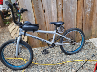
Sounds like you have quite the build! Unfortunately pics are no longer viewable. I'd love to get to the 2000w point lol. My whole setup is under 100$ canadian considering I had the drill batterys already.
I started out doing everything entirely with parts I already had, or could get free as discards from other people. I still do that as much as possible, as I still don't have much more money than I did then (maybe not any more, given all the recent inflation).
Plus...it's fun to see what I can misuse for my purposes that it was never intended to do****...I just now have some experience in what has a *chance* of working, which I didn't at the time.

****I do that with my music and other stuff as well, like the most recent song
Behind You Lie Many Unseen, by Amberwolf that uses some spoken elven intended for quiet "cinematic" music and some chants to make vocals for "rock" and "funk" sections at the end of the song.
Also I'm no electrician but if i were to get the 18v controller is it limited to the 250w? If I'm running a 12v motor at 18v won't the wattage go up too?
If you're running a 12v motor at 20v+ (whatever actual voltage those packs are at) with no current limiting (no controller to do PWM) you're already running it at much more than it's design wattage.
")
Sometimes that's ok, and sometimes it can damage the motor by overheating the windings or the magnets.
Also, running a brushed motor faster than it's design speed by enough RPM could cause the commutator segments to come loose, which will destroy the motor; you're unlikely to have this issue at your voltage, but go up to a few to several times it's orignal RPM or more and it might begin to be a concern. The smaller diameter the motor/comm is the less likely this is to be a problem, but get up into bigger forklift motors and it can be.
Some thoughts:
How hot does the motor get? The battery? What voltage does the battery drop to under load, from what voltage without the load, under various conditions (and what are the conditions)?
Just at a guess, if you had maybe a 5% slope (pretty shallow), you could be pulling 500 to 1000 watts out of the battery, with most of that turning into heat inside the motor. (also depends on the gearing ratio between motor and wheel, and hte wheel size, and the RPM the motor was designed to spin at).
There are calculators to figure out the required power to move at a certain speed with a certain weight up a certain slope (or just on the flats against wind resistance), that can guesstimate the power being used in total, for a given set of riding conditions; that's the power the the motor would have to provide in order to do that job. It would actually be getting *more* than that power from the battery, and the difference ends up as heat. (how much more, you'd have to be measuring under those condtiions).
I completely burned up the windings on my first little "unite" motor trying to chain drive the rear wheel with no controller.


 ) battery and motor seem to stay very cool warm at best. Just the terminals of the intermittent button get super hot. I was running it by just directly connecting the motor leads to the battery and everything worked great, was just super janky to ride. Either ripping full speed without stop or off and hard to work the terminals while riding.
 I got 2 heavy duty 20amp buttons on amazon for around 12$ and they sell 50 amp ones for a bit more. Think the 50s would hold the heat better?? It almost is perfect as is, just got to keep an eye on the heat


