• Hello ES! We could use some help to get us past the finish line on building the new knowledgebase for the forum.
    Can you donate? Please see our fundraising page. Thank you!

Bafang Canable Pro Master - discussion

DPC18RI

⚡ Regular
Joined
Jan 31, 2025
Messages
232
Location
Benelux
Bafang Canable Pro

Few weeks ago i noticed on Github this program "bafang canable pro" written by bart594 and what can i say, once i had it running it's just a ... Real master!
Link to YT video about bafang canable pro

Link to YT video with some of the updates sinds the first video

One thing to note, if you see not plausible value's for " Undervoltage cutoff (under load)" or "Undervoltage cutoff (idle)" or "recovery voltage" no matter if it is in this program or Open Bafang Tool or even in old Besst... Don't change them!


Canable Device V1.0 ( The hardware needed)

It is mentioned, to be sure you are good to go, use a STM32F072 based canable V1 which has already candlelight firmware in it. This FYSETC UCAN board (picture 5 below) with USB-C even comes shipped in nice plastic box.

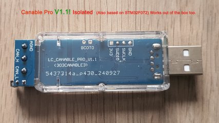
Canable PRO V1.1 ISOLATED also based on STM32F072 works also right out of the box. It has a transparant enclosure and some leds showing data traffic. Canable PRO V1.1 ISOLATED make sure you pick the isolated version here. This one (picture 2 and 3 below) has USB-A and you can use a usb extension cable with a length to your needs to keep the can wires with a shorter length.

Windmeile.de now offers a ready to use Bafang programming cable.

Bafang canable pro
mdi-9 is regularly working on the code adding extra features.
Link to github with latest changes.

He now have also ready to use builds for windows, linux and macOS also as arm64.

mdi-9 latest release V2.2 ( CANbus tool for Bafang ).
Windows users just select the win-x64.exe and install.

Picture 1 ready to use module from windmeile. 2 and 3 are the Canable V1.1 Pro isolated which works also right out of the box just like the "normal" v1.0 canable based on STM32F072 chip.


windmeile module canable.png20250731_154022.jpg20250731_154036.jpgBafang Canable Pro connection.jpgFysetc ucan.jpg


Important: Different canable manufacturers can use different positions for can H and can L and ground connection, so you have to read / follow the text printed on your canable!
Green wire needs to go to connection H (can High).
White wire needs to go to connection L (can Low).


-----------------------------------------------------
For those with a canable V2 or V2 PRO there is good news now, finally a good working candlelight firmware 2.5 from ElmüSoft even supporting CAN FD. Also you can install the correct windows usb driver. You can update your canable V2 with a few clicks without having to deal with the boot pins. Just install the ElmüSoft program "Hud Ecu hacker" and from within that program you can update your canable V2 or V2 PRO firmware to candlelight V2.5 firmware with can FD support.

And then your canable V2 or V2 PRO can work with Bafang Canable Pro too. Starting from release 1.6 which has the support for a canable V2 / PRO now added.

To download Hud Ecu hacker scroll down on that page until you see the bigger text "download and Installation" right below it you see the example and version but the button "download" you can click to download it.

If you don't like to read below, watch the video about it.

When you have Hud Ecu Hacker up and running, go over the icons at the top until it shows "USB driver and update firmware" click that and you are at the right place to upgrade / install firmware on canable V2 / PRO.
Select your adapter (canable). In next screen, if you need the correct winUSB driver for candlelight put a checkmark at " Install winUSB driver for candlelight". At bottom click install driver.

After that, under "update firmware" put checkmark at "Update firmware canable". Then below it click "Update firmware". The firmware updater will now open. Click "Enter DFU mode". In "target ID" Put checkmark at 00 .
At the bottom you can see "STM32G431 candlelight 2.5 Makerbase" already selected.

Click "upload". After the update is ok, you can click "verify". If all is ok click "Leave DFU mode". Now you can use your canable V2 / PRO too in Hud Ecu hacker and also in Bafang Canable Pro starting from release 1.6
----------------------------------------------------------

If you want to test your V2 / PRO when you are still in Hud Ecu Hacker to see your packets from your bike, go to main page screen, click "Control" button. Under connection select your "canable candlelight firmware" and click "Sniff mode". Then select " Snif terminal" and select your canable. Click "Configure". Set Baud rate 250K and ID lenght 29 bit. Command; i left it for wat it was.

Put a checkmark for "Show all packets". Put a checkmark for " Suppress repeating identical canbus frames" and then click the "Save" button.
And finally, click "Open" (next to configure button).
Switch your bike display on and if all good you should see your bike canbus stream. If you are done, click "Close".
Close all "Hud Ecu hacker" windows and open Bafang Canable Pro, You should see the name change for the adapter. Enjoy :)
 
Last edited:
Bafang firmware

Regarding "firmware update":
It is not a case as "one method fits all". It depends on which motor controller and even for the same motor there can be differences in method because of different hardware versions for that motor.

If someone can provide me for M400 controller version 2.1 the original firmware that would be great.
Also searching for latest 250 watt M410 CAN firmware 36 volt and BBS01B CAN 36 volt firmware.

Firmware update display's, for a same type of display but other hardware version, the "method" to update can change too.
Also if a display can be updatet when it is connected for example to motor "A" it does not mean the same display can be updatet when it is connected to motor "B".


If a controller update fails, the simple method to restore is using besst tool or maybe K1 flash if you have it. In case of a display update fail when it was connected to a controller, restore with Besst tool.

Firmware updates or trying to change settings using the program is at your own risk and responsibility.

Start or restart the program fresh. Also keep in mind the "auto off" time your display is probably set to 5 min. For all my tests i have it set to "auto off time = off".

Controller firmware update:

M820
version ? with display DPC245 / DPC080CB HW1.0 / DPC010CN HW1.0
Display needs to be on. Mode: Motor controller. Delay 300. Pick correct M820 firmware bin.

M560 version? with display ? (most likely also with DPC080CB HW1.0 / DPC010CN HW1.0)
Display needs to be on. Mode: Motor controller. Delay 300. Pick correct M560 firmware bin.

M420 Hw version 2.2 same as above but user Deco used a delay 400 and of course pick
the correct M420 firmware bin.


CR S10F.350.FC (Hardware version 1.1) Hub controller
Method 1
With display connected and ON.
Mode OLD motor controller. Delay 300. Pick correct "version" file. Turn OFF display.
Click "Start update", when "waiting controller ready" is shown, Press display ON and HOLD it pressed down!
till "progress" count shows 100% in program then let go on / off button.

Method 2
NO DISPLAY connected (but instead of a display, a stub will be connected)
Mode: Old motor controller. Delay 300. Pick correct "version" file.
Insert stub (where normally the display is plugged in) and then click start update procedure.
When finished, remove stub and reconnect a display.

M410 V2.0 and Hub controller CR S10F.350.FC V 4.0
Mode "M410 V2.0 / Hub CRS10F V4.0".
Delay 300
Method 1 and 2 same as above for CR S10F version 1.1
but instead of "old motor controller" you now use "M410 V2.0 / Hub CRS10F V4.0" mode.

M400 HW 1.0
Method 1
With display connected and ON.
Mode OLD motor controller. Delay 300. Pick correct "version" file. Turn OFF display.
Click "Start update", when "waiting controller ready" is shown, Press display ON and HOLD it pressed down!
till "progress" count shows 100% in program then let go on / off button.

Method 2
NO DISPLAY connected (but instead of a display, a stub will be connected).
Mode: Old motor controller. Delay 300. Pick correct "version" file.
Insert stub (where normally the display is plugged in).
!! Click start update procedure !!
UNPLUG stub and immediately plug back in (must be done before timeout!).
When finished, remove stub and reconnect a display. Link to YT video both methods

M400 HW 2.1
I have one but i have only an older bin compared to the one in controller.
If someone can provide me original bin CRX10BC4314E102093.0 i can test it too.


DISPLAY firmware updates
Display connected the normal way and ON.

DPC245 / DPC080CB HW 1.0 / DPC010CN HW1.0
Connected to M820 / M400 v 2.1 or CR S10F.350.FC v 4.0 hub cntrl.
display update, link to YT.
Display must be ON.
Mode HMI. Delay 300. Pick the correct display bin. Start update procedure.


DPC18 HW 1.4
Connected to CR S10F.350.FC (v 4.0) / M400 (v 2.1) or M820 /
Display must be ON.
Mode: "HMI DPC18 1.4" (that mode is, for now, ONLY for DPC18 hardware version 1.4 ).
Delay: 300. Pick correct DPC18 HW 1.4 bin file. Start update procedure.
Link to YT video firmware DPC18 hw 1.4

DPC18 HW 1.0 (and perhaps HW1.2) not implemented in code.

DP E160.C 1.0 and probably DP E161.C 1.0
Connected to M820 / M400 v 2.1 or CR S10F.350.FC v 4.0 hub cntrl.
Display must be ON.
Mode " HMI DPE160". Delay 300. Pick the correct display bin. Start update procedure.
 
Last edited:
For voltage cutoff under load and recovery voltage...
The system / controller i tested with is 43V system CR S10F.350.FC 4.0 hub motor controller.
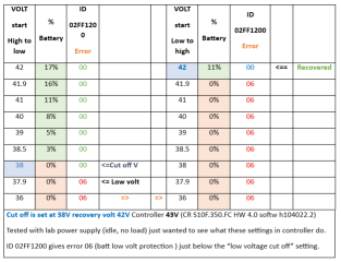
In Canable program "Undervoltage Cutoff (under load)" shows 38V and what is / was named as "Undervoltage Cutoff (idle)" shows 42V.

I wanted to be sure about what is my cutoff and recovery voltage. So i started with a lab power supply at 42V and slowly turned power supply down. (In the picture 1, left column from top to bottom). As soon as i reached 38V (Cutoff) the battery % changed to 0% and 0.1V lower at 37.9V the error 06 showed up in my canbus program.

When i was down to 36V i started to up the voltage in the columns on the right. Note that the 0% battery stayed as also the 06 error which is low volt battery protection until i reached my 42V recovery voltage. And at that point the error changed to "00" and batt percentage jumped to 11%.
So i'm pretty sure that my 3800 is cutoff and 4200 is my recovery voltage.

CRS10F.350.FC LOW VOLT test.png
 
Last edited:
uncomment those 2
Done. And changed the title of the field undervoltage recovery also.

Perhaps you should fork the repo yourself and make a pull request. This little changes can be done directly in the webbrowser, so you don't need any knowledge about using git locally on your PC. ;)

regards
stancecoke
 
The next i found (in my case) brand new M400 Can Controller connected to M400 motor. Under "Info" tab the info for "sensor" shows nothing after clicking "Sync". (It does for controller and display).
I searched true main.js and found 2 identical lines. I commented one out although not sure why they are identical and it's not related to the problem. Below it i added 4 extra lines which seemingly were missing. Now under "Info" tab the data for "Sensor" (CANBUS torque sensor) shows up too.

In main.js

Code:
// Sensor Data (Keep existing cases, ensure needsSensorUpdate is set)

                        case 'sensor_realtime': sensorRealtime = parsedEvent.data; needsSensorUpdate = true; break;
                     // case 'sensor_realtime': sensorRealtime = parsedEvent.data; needsSensorUpdate = true; break; // DPC18RI disabled it (2 same lines?) *********
                        case 'sensor_hw_version': sensorOtherInfo.hwVersion = parsedEvent.data?.hardware_version; needsInfoUpdate = true; break;  // DPC18RI added
                        case 'sensor_sw_version': sensorOtherInfo.swVersion = parsedEvent.data?.software_version; needsInfoUpdate = true; break;  // DPC18RI added
                        case 'sensor_mn': sensorOtherInfo.modelNumber = parsedEvent.data?.model_number; needsInfoUpdate = true; break; // DPC18RI Added
                        case 'sensor_sn': sensorOtherInfo.serialNumber = parsedEvent.data?.serial_number; needsInfoUpdate = true; break; // DPC18RI Added

Would be great if this could be added too so that others with a CAN torque sensor can see "info" sensor data too.

(I add my name and many times also **** behind the things i add or change because i could then easily find back the things i altered because it is al Latin to me...
 
Perhaps you should fork the repo yourself and make a pull request. This little changes can be done directly in the webbrowser, so you don't need any knowledge about using git locally on your PC. ;)

regards
stancecoke
About that, it's not my cup of tea. I leave that to the masters like you. Maybe it sounds like i find these things in an instant but no way. I staring at the code for hours, days... Because like i told before it's all Latin to me. But eventually (not always) i get it working although by that time my brain is over cooking lol. So regarding pull request i leave that to the masters :)
 
I leave that to the masters like you
As said, just try it directly in the Github web page. It's no witchwork at all.
I've added your suggestions, but I can't test it, as I have no CAN sensor.
I've merged the additional tab from @mdi also, but in future, we should work with pull requests, this makes life much easier.


I found, that the curves in the assist tab are only shown in the tab you've synced first. However, this bug may be negligible, as you will not be working in both tabs.

regards
stancecoke
 
Last edited:
About the curves in the 2 assist tabs, that i can not test because none of my controllers responds to param. 6010 so i can only use the second assist tab (i added screenshot from it to the first post).
However about those 4 extra lines i mentioned for the "sensor" info tab, no worries, that is tested and working. Before that nothing showed up for "sensor info" (at least not for this M400 torque sensor with can communication) and after adding those 4 lines, the data do show up. See picture.

Info sensor.png
 
Last edited:
Regarding M400 with torque sensor with CAN signals, torque sensor seems to send every 10ms? And i noticed under "Debug" tab that "Communication log" was scrolling heavily / overflooded with these torque signals every 10ms from the M400. Different motors, different behavior...

In main.js is a section "skip some messages so log from UI is not overflooded" i added the torque sensor: 'sensor_realtime',

Code:
//skip some messages so log is not overflooded
                    const typesToSkipInUILog = [
                            'sensor_realtime',   // Added by DPC18RI for m400 CAN / torque sensor with CAN signals every 10ms? ******
                            'display_realtime',
                            'controller_realtime_0',
                            'controller_realtime_1',
                            'display_data_1',
                            'display_data_2',
                            'display_data_lightsensor',
                            'display_autoshutdown_time',
                            'controller_current_assist_level',
                            'controller_calories',
                            'controller_speed_params'
                          
                        ];

After adding that line looking again at "communication log" under "debug" tab, it is not overflooded anymore. I then checked under the tab "sensor" "real-time data" just to be sure. Turning the torque axle the cadence value changes up real-time and putting force on it, the 750mV torque value also go's up.

This will be the last one for this M400 motor, i give up finding things. Every section of the program seems to work ok now for this type motor. I made this thread so we can exchange / compare data / findings on how different motors behave in this program.

So if others have a different motor with torque sensor with can signals, does it flood the "communication log" too under "debug tab"?
Have you missing data under "info" tab for sensor? (if your sensor has can signals).
Other sections where no or only some data shows up? Controller? Display?
Are the voltages for "undervoltage (under load)" and "undervoltage recovery (idle)" plausible for your motor / controller?

Or is there only a handful of people who uses this program although the cost for a Canable is dirt cheap? :)
 
Last edited:
Or is there only a handful of people who uses this program although the cost for a Canable is dirt cheap? :)
I guess we would have to spread the information, that you can tweak your CAN Bafang with the very cheap Canable in more channels, like the German pedelecforum.de, as very popular discounter bikes in Germany are using Bafang CAN systems, the users will not be here in the DIY forum. I'm not active there any more...
And of course, having to cut the extension cable and wiring the canable is a hurdle, perhaps we would have to prepare the first 20 cables and sell them for 20€ until a Chinese company will produce them in series and the usual webshops will sell them ready for plug'n play. ;)
 
Last edited:
If i make a small video for YT? I don't know, my English writing is not so good but English speaking in a video trying to pronounce correct is terrible. To be sure i put mostly subtitles too lol.
Pedelec forum, I'm there but post rarely because i need to use a translator.
EDIT: Some moments ago i did post a message there in a Bafang can thread regarding "bafang canable pro master".
 
Last edited:
Hi, I've also discovered the wonderful work of bart594 which takes the bafang hacking process from like $200+ and a lot of messing around, to just <$20 for a CANable and extension cable on Aliexpress. Really surprises me that there isn't more buzz and developers helping out with this given how much more accessible it makes things (of course there is OpenBafangTool but it doesn't support CANable yet).

My M600 also spits out sensor_realtime data, so I too added it to the list of messages to ignore. I don't get any info for battery or assist tabs, but other tabs seem to be fairly complete. I successfully changed the speed limit.

I will have another play later with mdi-9's fork (GitHub - mdi-9/bafang_canable_pro: Bafang Besst software replacement for M500, M510, M560, M820 etc) which supposedly add support for M820 and see if it also works with M600. (Ideally there wouldn't be different forks for different motors and it would just work seamlessly with whatever info it gets, so it would be nice if forks are merged in eventually)

I have a lot of experience with NodeJS development and open source, but nothing at all with CANbus, but I am happy to try help where I can.


edit: For reference, I bought this CANable and this extension cable which I then cut in half, stripped the wires, twisted and soldered the pairs together, then inserted the black (ground), white (can L), and green (can H) wires into the terminals on the CANable using the markings on the bottom of the board to know which goes where.
 
Last edited:
My M600 also spits out sensor_realtime data, so I too added it to the list of messages to ignore. I don't get any info for battery or assist tabs, but other tabs seem to be fairly complete. I successfully changed the speed limit.

I will have another play later with mdi-9's fork (GitHub - mdi-9/bafang_canable_pro: Bafang Besst software replacement for M500, M510, M560, M820 etc) which supposedly add support for M820 and see if it also works with M600. (Ideally there wouldn't be different forks for different motors and it would just work seamlessly with whatever info it gets, so it would be nice if forks are merged in eventually)

I have a lot of experience with NodeJS development and open source, but nothing at all with CANbus, but I am happy to try help where I can.

Welcome :)

Is your battery Bafang? Some 3th party's also have Bafang can protocol. Anyway, your battery needs to have canbus before it can show up in "bafang canable pro master" (i like that name). Bart594 has a homemade batt. So he could not test if "battery" tab shows data. I have for the moment no Bafang battery.

mdi-9 fork, he added that tab for M820 and that M820 "tab" works for my M400 too. stancecode merged it and he did also all updates i posted. Not sure if he added the last one to stop overflooding. I saw he made a pull request. So for now i think stancecoke has the most complete? repo with the proposed changes.

(Ideally there wouldn't be different forks for different motors and it would just work seamlessly with whatever info it gets

I proposed on github to build in another extra check that if param 6011 and 6012 and startup angle is received but 6010 gives error because of data lengt is 7 or lower instead of the expected 64 bytes, to still parse the data and making the assist ratio column showing NA. That should then work for all controllers i guess. And with 1 "Assist" tab. But security counts too and yep if one of the expected params is missing (because controller does not have it) then show nothing under Assist tab. I understand that too. That way because of missing param you can not change value's and keeps controller safe :)

mdi-9 added an extra tab, that is fine for me too, really happy with it! Just guessing there are more motors which will not respond to the first "assist" tab but will do on the "M820" tab.
 
I’ve been thinking about trying this tool and your post actually cleared up a lot. Good tip about not messing with the undervoltage values if they look weird - I probably would’ve done that by accident
 
I've added eslint to the project for better development.
This expose bunch of bugs which i fixed right away.
I also include Your findings @DPC18RI

Nice! Is there appetite for a TypeScript conversion? Would help catch bugs earlier and make development easier I think but might take a bit of work...
 
Too much work I think. There will be nice to have some modern framework here like Angular or React and split this tabs into seperete components. All UI code in one file not clean but simple.
 
Can now confirm that the M820 assist tab also shows assist curves for my M600. Still not sure which parameter will make the throttle I added work from a standstill though (it only works once the bike is going). Maybe this is not configurable on my controller or something.
 
Can now confirm that the M820 assist tab also shows assist curves for my M600. Still not sure which parameter will make the throttle I added work from a standstill though (it only works once the bike is going). Maybe this is not configurable on my controller or something.
I think it's maybe hardcoded that way in the firmware. Some mid-motors you need to reach 6 a10 km/h before you can use throttle. (Is what i once had read somewhere). Probably to safeguard the motor when from standstill pulling throttle wide open.
 
With last commit i've added support for Raspbery Pi zero w. Tested and working fine - no driver issues.

Now it would be possible to hide both devices in bike frame. Create wifi hotspot on Rasp.

With that we have access to the app from phone or tablet and can change all params on the fly.

 
Back
Top