DIY Toroidal Axial Flux PM

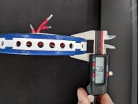
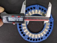
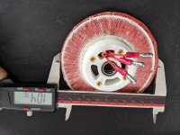
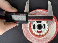
Can you clarify the dimensions of all your bits? Especially the inner and outer radius of the magnet circle?

From your last scope shot i see 35hz=2100erpm, 12pole pairs, 0.8V so you're somewhere in the region of 210kV

I've got a thread going about trying to make a radial flux iron core motor but I'm completely failing to get stators... One Chinese company wanted 1200usd for 5 stators to my design... I cannot find off the shelf sensible stators, they're all crazy pole numbers like 36n42p.

So I'm possibly back to axial flux coreless. The idea of a fully 3d printed motor on my ebike is still appealing, but I'll be limited to about 120mm (probably 150mm absolute max). I'll need about 1/3 your kV so possibly going to multi rotor or increasing the diameter would be enough.

The no load efficiency and spin down times are also very very attractive.

How much does this latest one weigh? I can accept up to about 2kg which is probably vastly more than this.
 
~
mxlemming said:
How much does this latest one weigh? I can accept up to about 2kg which is probably vastly more than this.

Also, interestingly, the Mk6 weighed nearly the exact same as the Mk5 at 399g. Each rotor with the iron back and the magnets weighs ~150g each. and the stator and hub is about 100g.

I would love to do a multi-rotor down the road, I just need to get good at making one first for now though. but it's certainly getting there
 
HalbachHero said:
~
mxlemming said:
How much does this latest one weigh? I can accept up to about 2kg which is probably vastly more than this.
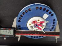
Also, interestingly, the Mk6 weighed nearly the exact same as the Mk5 at 399g. Each rotor with the iron back and the magnets weighs ~150g each. and the stator and hub is about 100g.

I would love to do a multi-rotor down the road, I just need to get good at making one first for now though. but it's certainly getting there

This is good. Looks like i could easily maintain a similar size while increasing the magnetic radius 10mm which would give a lot more torque. Torque roughly increases with radius squared, and kV down proportionally.

Then stack a few layers together (I think this is where axial flux comes into its best) and the kV could be reduced by a lot.

Actually for a motor this size, your kV is already quite low.

The biggest question then is what happens when you start throwing large amps at it. Is there a limit at which it just stops increasing torque?

Did you ever try this in FEMM?
 
There is no way I am going to find it now, but I remember reading a paper a year or two ago that talked about optimization of an axial flux motor, and it was found that there is a ratio of inner to outer diameter that you want to maintain, if your magnets are too long, you end up with larger gaps on the outer diameter. I feel the halbach help with filling those gaps too.

being naive, Originally I wanted to make a motor the size of a bicycle wheel, im sure I will try a larger one in the future too, but keeping things from bending and pulling apart at larger diameters could get challenging I would think. I would love to see someone else's take on this.

As far as current goes, I have only ever seen it pull 32A. That was the Mk3 with a propeller on it (video on Youtube). that had the same conductor as this. 20 strands of 32 gauge. I am curious what the upper limit of current is, or what the torque curve really looks like.

I did some FEMM stuff earlier in the thread. But not really for the changes that I have made lately.

As far as Kv goes, I believe that if I can continue to improve tolerances, and fit all 10 turns into the 6.5-7mm that I am expecting, that I can drop the KV to about 1/2 of what I had with the Mk5. hoping for 120, or maybe even as low as 100 with all 10 turns.
The 7 turn stator was a bit disappointing, but I really think the air gap being larger is the reason for that.

I also heated the stator and was able to flatten it a bit, so that's cool. unfortunately the geometry of the rotor/hub do not allow for me to easily get things closer. I would need to make a whole new stator or rotor.

thinking about the next iteration of this, there is improvement that can be made to the rotors still. There is still some flux leaking out the back, so I would like to try more metal behind the magnets, but I would either have to fashion a washer myself, buy one, or have one custom laser cut. I am really leaning toward the custom, as I cannot find the exact size that I want, and I have already modeled something that I think would work well. Its going to cost about $100 USD for 2 or $125 for 4. I may pull the trigger on two of them and see how it goes, but I'm having a hard time justifying that cost on two small pieces of metal.

this hobby is a little expensive...
 
Do you have ideas on how to improve the next iteration? If not, what are the issues you'd like to fix?

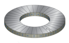
Have you found a good source for halbach arc / wedge shaped axial flux magnets? These should eliminate the length / gap / loss you mentioned. I'm not sure what is ideal, If you want the halbach magnets thin or full size like this picture.halbach arc magnets.PNG

Halbach, are you getting any special size or material for the washers you need?
 
Jrbe said:
Do you have ideas on how to improve the next iteration? If not, what are the issues you'd like to fix?

Have you found a good source for halbach arc / wedge shaped axial flux magnets?

Halbach, are you getting any special size or material for the washers you need?

So for the next iteration I think that I want to do more turns. This has been an issue with the jig that I used to wind the last stator. I have ideas on how to improve. Just need to get the printer to work. Improvements to the winding jig will hopefully keep the wires more in their place and help improve performance slightly.
Also I want to shrink the air gap to as small as I can get it, which at this point is getting a super flat stator and designing the parts to have the correct gap. Again, pretty much just need the printer working.
I will also try to add hall sensors to one of these versions.

As for the rotors. I would love to reduce the flux leakage out of the back of the rotors, and I would potentially like to swap the shaft in the middle of the rotor to a custom bushing of some kind to ensure a straight shaft for the bearings to sit on.


Early on when I was brainstorming ideas, on where to begin, I looked into getting some of these custom arch shaped halbach magnets. While I think they might provide a benefit. I would also like to make this motor using as cheap of parts as possible. Ideally others can make something like this if its easy enough. by keeping the magnets as bar magnets they are much easier to source, and generally for much cheaper.

This is the reason I am hesitant to move forward with the custom rotor backing. The part I am using is a TRB-4458. Its very close to the inner and outer diameter of the magnets how they sit on the rotor, and its 1.5mm, which if you look at some of the FEMM data I compiled earlier on in this thread you will see I found to be optimal given my magnets and their arrangement

The other part of me wants to optimize the hell out of this. So we will see where it actually ends up. I have another project I have slowly been working on on the side that might change the game a bit.
 
I have an idea for the stator. Its not fully fleshed out yet but might help this along.

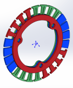
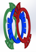
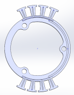
This is drawn up to mxlemming's motor schematic he has in his thread and Halbachhero's outer ring spec. Not sure any of that makes sense together but wanted to get you guys the idea.

These are 2mm wide with a stack width in the middle of 6mm - no idea if thats ideal or not.. With this you could wind each group of coils then bolt them together. The 3 drive nubs on the inside double as holders for conductive bushings to get the power to the coils and also allow stacking of stators / jumping to the next stack / group. The notch on the right side (light grey outer stator) is for the wire routing between the groups (right side slot.)
Modular outer stators.PNG Stator stacked view.PNG Outer stator.PNG This would trap heat in the wire. Could add some holes to allow air in and out.

I did not optimize / clearance them between each other yet and the center version needs the notches and other stuff added. This is done in Solidworks 2019 as one file with a center (poor) and an outer (decent) configuration. I attached a zip of the Solidworks file and step files, just remove the .txt in the file name to open it. Feel free to use or disregard. I could help some with it as well if you guys want. I would like to build some of these motors as well.

To add some strength you could add fiberglass tow to the wire as mentioned previously. There are also fiberglass and kevlar sleeves. These are woven tubes that can stretch and conform to different shapes. These could work well a few places here. I also keep thinking of a uv cure epoxy or maybe SLA resin could help as well.
 

Attachments

  • Stator.zip.txt
    788.2 KB · Views: 31
Very cool models. Maybe I am missing something, but mxlemming's motor is radial flux. the conductor would have to travel radially in order to be used in an axial flux motor.

I do however really like the idea of using something to relieve stress on the conductors going into the stator directly by the use of some bushing or other part. I might steal that idea

Also the winding pattern in mine is a bit different I believe due to the overlapped windings
 
Am also quite confused by jrbes model.

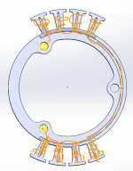
Could you put some magnets and copper in it to explain?
 
Yellow would be a conductive bushing.
Orange is wire.
Outer stator.PNG.png
One for each phase, rotated 120° each. So 2 outers and one center.
It's the first thing I thought of after seeing this,
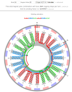
LCM24,22.PNG.png
For axial flux the T shape could change to a picture frame wedge shape and rotate maybe 5° and have the wire go up and around. I didn't make it very clear. Halbach seems to have his coils sequence in phase order. This same 3 separate phases / pieces could work there as well, just spread out the coils in the correct order.
 
I understand what you are saying and I get how it could be adapted to work with an axial-flux style motor, and if it was made of iron, it could work as a type of squirrel cage. and could still worked with the overlapped windings. however I think this would be a complex part to create, and the worst part would be trying to wind the stator. I am not sure how you would hold the conductor in place as you went.

I would suspect that if you took that same concept and implemented it in a PCB, it might work. I have given some thought lately to making a layered PCB. I think that would result in the most perfect stator possible, but obviously is not entirely DIY-able at least not in a way I am willing to attempt.

I want to see how far I can get with making these without custom parts first (I think I am getting close to that point). Once I cant take it any further, I will likely see how much I can squeeze out of it by ordering custom parts and spending a bit more money on it.

Until then I will continue to iterate on the design and the process of how to make it. I have little experience building actual things like this, so every step of this project has been a learning process, and I have been enjoying the progress lately.
 
I was thinking it could all be SLA printed.

Wire could be held in place with little tabs like you see in an oring groove or a wire channel with opposing holder tabs.

If built in a clever way you could remove the left side of the ring to allow winder access to the inside.

I'll throw some ideas together in a separate post so I don't clutter yours up.
 
Jrbe said:
I was thinking it could all be SLA printed.

Wire could be held in place with little tabs like you see in an oring groove or a wire channel with opposing holder tabs.

If built in a clever way you could remove the left side of the ring to allow winder access to the inside.

I'll throw some ideas together in a separate post so I don't clutter yours up.

SLA might not handle the heat very well, so I would think that it may end up thermally limited. But, you SLA might be a step towards making a mold for casting perhaps.

Its certainly an idea I have not considered before. I'll follow your post, curious what you come up with.


So I was able to get the new jig (part 1) printed. This will be a 2 step process this time. I an going to wind it on the jig, and glue it. There is a thin section that will go down before I start winding and allow me to pry the stator off easier. Ill wind the stator, epoxy it in place, pop it off when the epoxy is less workable, and move it to another part I have yet to print that will align the hub properly and allow me to fill the voids between the legs of the stator. This step could likely be where a vacuum chamber could help, but for now I will just 3d print a press

resized-image-Promo - 2021-09-18T232020.683.jpeg
resized-image-Promo - 2021-09-18T231950.888.jpeg
resized-image-Promo - 2021-09-18T231917.088.jpeg
 
I don't quite understand but that looks quite serious.

Another question... Did you measure the inductance of your motor? I'm worried it might be crazy low.

If you've not got an ESC that can measure you can put a capacitor (PP or ceramic, few uF from memory) across two of the legs and give it a little tap with voltage while watching it with a scope.

Start with a low voltage... Last time i did this i generated about 0.5 kV from tapping it with a 24Vsupply...
 
Ill take photos as I wind it. that should make it more clear.

I have not yet measured inductance. This is another thing I need to really learn about. The only ESCs that I have are cheap ones. The flisky is absolutely in my future. just haven't ordered it yet (I'm assuming you could measure it with one of those)

Also, from my reading, it would seem that low inductance could be a good think, but I may need hall sensors to be able to turn it efficiently. Is that understanding correct?
 
Low inductance for our kind of motors is usually a problem rather than a help. If you consider 30kHz switching, 50%duty, that's about 15us with half the bus voltage going into winding up the inductance (the other half pushes against back EMF)

So consider say a 50uH motor (like on my bike)... 50Vrail.

V=Ldi/dt so di/dt is 50/50uH = 1A/us =15A ripple.

Considering the motor saturates at about 70A this is quite significant.

Your motor has no iron so it'll probably be nearer 5-10uH. Anything below about 10uH basically doesn't work with FOC in my experience and anything below 25 or so works badly.
 
Is it worth breaking up the coils into groups? You could then wire in series or parallel to get inductance in a better place.
 
If the low inductance causes controller issues, you can place inductors in series with the phase wires between the motor and controller. While this adds some loss, it can be pretty minimal with the right inductors.
 
mxlemming said:
Low inductance for our kind of motors is usually a problem rather than a help. If you consider 30kHz switching, 50%duty, that's about 15us with half the bus voltage going into winding up the inductance (the other half pushes against back EMF)

So consider say a 50uH motor (like on my bike)... 50Vrail.

V=Ldi/dt so di/dt is 50/50uH = 1A/us =15A ripple.

Considering the motor saturates at about 70A this is quite significant.

Your motor has no iron so it'll probably be nearer 5-10uH. Anything below about 10uH basically doesn't work with FOC in my experience and anything below 25 or so works badly.

Interesting. And if I was to use a flipsky or something that could measure inductance, would it be reasonable to assume that if it cant drive it well, it cant read the inductance well?

Also it seems hall sensors could help but maybe are not accurate enough?


Jrbe said:
Is it worth breaking up the coils into groups? You could then wire in series or parallel to get inductance in a better place.
correct me if I am wrong, but trying to get more inductance out of it would only reduce the Kv right?


fechter said:
If the low inductance causes controller issues, you can place inductors in series with the phase wires between the motor and controller. While this adds some loss, it can be pretty minimal with the right inductors.
I was reading about this, but understood the losses would effectively counteract any efficiency gained with FOC. Could you elaborate on what the right inductor would be? I'm not really sure where to begin there.
 
HalbachHero said:
Jrbe said:
Is it worth breaking up the coils into groups? You could then wire in series or parallel to get inductance in a better place.
correct me if I am wrong, but trying to get more inductance out of it would only reduce the Kv right?

I'm not sure of the answer. I'd expect it's some tradeoff.
My assumption was you were going to wire each phase in a series of coils.
If you broke each phase up into an even number you could try different coil configurations by wiring them to what you're trying to achieve or test. Things don't always go as expected, having a way to reconfigure the coil groups could be worth the extra effort, or not.
 
HalbachHero said:
mxlemming said:
Low inductance for our kind of motors is usually a problem rather than a help. If you consider 30kHz switching, 50%duty, that's about 15us with half the bus voltage going into winding up the inductance (the other half pushes against back EMF)

So consider say a 50uH motor (like on my bike)... 50Vrail.

V=Ldi/dt so di/dt is 50/50uH = 1A/us =15A ripple.

Considering the motor saturates at about 70A this is quite significant.

Your motor has no iron so it'll probably be nearer 5-10uH. Anything below about 10uH basically doesn't work with FOC in my experience and anything below 25 or so works badly.

Interesting. And if I was to use a flipsky or something that could measure inductance, would it be reasonable to assume that if it cant drive it well, it cant read the inductance well?

Also it seems hall sensors could help but maybe are not accurate enough?


Jrbe said:
Is it worth breaking up the coils into groups? You could then wire in series or parallel to get inductance in a better place.
correct me if I am wrong, but trying to get more inductance out of it would only reduce the Kv right?


fechter said:
If the low inductance causes controller issues, you can place inductors in series with the phase wires between the motor and controller. While this adds some loss, it can be pretty minimal with the right inductors.
I was reading about this, but understood the losses would effectively counteract any efficiency gained with FOC. Could you elaborate on what the right inductor would be? I'm not really sure where to begin there.

The flipsky should be able to measure the inductance ok. I've successfully read 10uH motors and even 6uH motors..

Rewiring the same motor to change the inductance will also proportionally change the kV.

Inductors in series work fine... But... They'll be pretty big, as in similar scale to the iron you saved from the motor...

Hall sensors are pretty good. They become problematic at high current, when the placement is such that the high field from the wires impacts them.
 
mxlemming said:
The flipsky should be able to measure the inductance ok. I've successfully read 10uH motors and even 6uH motors..

good to know. I will buy that soon. I bought a really cheap LCR meter that I'm hoping will do the trick for now. We shall see

mxlemming said:
Hall sensors are pretty good. They become problematic at high current, when the placement is such that the high field from the wires impacts them.

I think I like the sensored approach the most. I've been thinking about how to incorporate them into the stator, and I think I have some ideas, but I don't really know much about them. I was reading that they should be spaced out 120* apart. Should each sensor align with a different phase? or should it be an exact 120* and they all align with the same phase?


Jrbe said:
I'm not sure of the answer. I'd expect it's some tradeoff.
My assumption was you were going to wire each phase in a series of coils.
If you broke each phase up into an even number you could try different coil configurations by wiring them to what you're trying to achieve or test. Things don't always go as expected, having a way to reconfigure the coil groups could be worth the extra effort, or not.

I would expect all coils in series to give me the highest inductance and lowest Kv, if I wound some coils in parallel I would suspect that it would increase the max current it could handle and lower the phase resistance. but with that I would suspect to have a lower inductance do to the fewer turns, but maybe my understanding of that is incorrect....
 
Also, in googling the subject of using FOC to drive low inductance motors. I came across a video of a gentleman Benjamin Vedder that shows he is able to drive a very low inductance, and large motor using FOC in a VESC 75 controller. I saw it on the internet, so it must be possible :)

[youtube]fbK2dcoYS7g[/youtube]
 
HalbachHero said:
Also, in googling the subject of using FOC to drive low inductance motors. I came across a video of a gentleman Benjamin Vedder that shows he is able to drive a very low inductance, and large motor using FOC in a VESC 75 controller. I saw it on the internet, so it must be possible :)

[youtube]fbK2dcoYS7g[/youtube]

It is possible... But there's a few factors
1) the deviation from sinusoidal of the back emf
2) the current being pushed (more is actually kind of easier up to the point that the little inductance causes over current faults)
3) the difficulty in tuning. Vedder wrote the code. He stands the best chance of knowing exactly how to make it work.

Iirc that motor is like 1.5uH so if running 55V that's up to 36A/us ripple. The pwm is normally 30khz switching so there will be something of the order of 275A of ripple. I've not re watched that video to find the exact parameters.

There are mitigating factors here. Possibly it's not really that low inductance or the pwm frequency is boosted or... Something...

Anyway, you can run FOC with ultra low inductance it's just ugly. The video I posted was 1uH motor spinning that fan with about 20V in FOC. It ran but it was ratty.

BLDC mode also has issues with low inductance, but it's a generally more forgiving algorithm.

Check zombiess video on inductance and ripple for a really good explanation.

It will run your motor I'm pretty sure.
 
Back
Top