components identification

raedy07

10 mW
Joined
Jun 23, 2024
Messages
23
Location
Spain
hello everybody here,
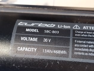
my name is Radek and i recently bought a defect SPECIALISED TURBO ebike from 2015. looking at d troubleshooting diagramm i'd say something wrong with d battery. upon opening i see 2 (mother)boards, i've added pictures. could it be 1 is d BMS and d other d controller/invertor? because i see no controller anywhere else.

thanx for all feedback!
 

Attachments

  • Spez batt-1.jpeg
    Spez batt-1.jpeg
    149.5 KB · Views: 23
  • Spez batt-5.jpeg
    Spez batt-5.jpeg
    331.8 KB · Views: 23
  • Specialized side.jpg
    Specialized side.jpg
    301.1 KB · Views: 23
The first picture is also part of the BMS. The actual motor controller must be somewhere else. It might be inside the motor.
You could measure the individual battery cell group voltages from the balance connector to see if the cell voltages are in the healthy range.
 
The first picture is also part of the BMS. The actual motor controller must be somewhere else. It might be inside the motor.
You could measure the individual battery cell group voltages from the balance connector to see if the cell voltages are in the healthy range.
right, i wouldn't expect motor controller in battery either, just didn't see it anywhere else :unsure:
all cells seem to be at 3.98V. 10S.
i contacted SPECIALIZED, they actually said motherboard was d problem, but it's not available anymore. for a 2015 model
:sick:
so i suppose problem 1 of the 2 in d pictures attached. just don't know which one, no obvious defects (burns) visible. any hints how to fix this? a universal BMS possibly? probably won't fit in d batt.casing, but as long as it works.... :cool:
where could i find a suitable one?

cheers!
 

Attachments

  • Spez batt-8.jpg
    Spez batt-8.jpg
    526.5 KB · Views: 4
It’s strange that they said the problem is the motherboard, but didn’t specify the motherboard of the BMS or of the controller.
 
right, i wouldn't expect motor controller in battery either, just didn't see it anywhere else :unsure:
all cells seem to be at 3.98V. 10S.
i contacted SPECIALIZED, they actually said motherboard was d problem, but it's not available anymore. for a 2015 model
:sick:
so i suppose problem 1 of the 2 in d pictures attached. just don't know which one, no obvious defects (burns) visible. any hints how to fix this? a universal BMS possibly? probably won't fit in d batt.casing, but as long as it works.... :cool:
where could i find a suitable one?

cheers!
so you tested the cells and all are good. did you test the total pack voltage you get after the bms?

about compatible bms, you have to see if the only cables coming out from this battery are positive and negative terminal or if there is any other cable that would communicate with the bms.
 
so you tested the cells and all are good. did you test the total pack voltage you get after the bms?

about compatible bms, you have to see if the only cables coming out from this battery are positive and negative terminal or if there is any other cable that would communicate with the bms.
yes total V is around 39.8. measured directly at d cells. no output further down d line.

i'll see how many cables there are tomorrow.
thanx!
 
For what it’s worth you could disconnect the motor cable connector down by the motor. If it has 3 big pins, and 5 or 6 small pins, then it’s likely the controller is located upstream. If 2 big pins and several small pins (for PAS, etc.) then the controller is likely located in the hub motor housing. If the former, you could try to follow the cable, and see where it enters the frame. I’m guessing the controller is above or below the battery, inside the downtube, depending on which end the battery contacts are located in the frame.

Does your model have the wireless display?
motor connector has 3 big pins. display has a 5-pin connector.
battery contacts on top. downtube seems otherwise empty; is d 3-pin motor connector not a safe indicator that controller is within d motor housing?
start-up LED-test as well as opinion from 'specialised' indicate a batt.problem. as cells are good that would leave d BMS - right?
if so, and BMS not repairable, do i best get a replacement? from GRIN or GREENBIKE for example?
 
as foreseen my components don't want to communicate with each other after i replaced the original BMS with a simple one. charging battery is possible, lights are on but motor doesn't react. could a simple solution be to install a throttle directly to the motor-controller? establish a battery-throttle-motor connection somehow? (i haven't opened that one yet). i could still pedal assist but control motor-assistance with the thumb (instead of pedal-sensor).
any thoughts on this idea?
 
for lack of better ideas, i open the motor. to do that, had to remove d spokes - never seen an userUNfriendlier design :(((( in order to get to d controller, also d 2nd half of motor-casing (brake-rotor side) needs to be removed. but 1st d FREEHUB - i am stuck. could d two recesses on 1 side and 2 holes on other side of shaft have anything to do with it? i attached 2 pics.
there is a tiny worm-screw. after removing it i try to gently lift hub with 2 screwdrivers, but no movement. does it need a puller?
 

Attachments

  • motor2.jpeg
    motor2.jpeg
    341.9 KB · Views: 12
  • motor1.jpeg
    motor1.jpeg
    191.5 KB · Views: 11
for lack of better ideas, i open the motor. to do that, had to remove d spokes - never seen an userUNfriendlier design :(((( in order to get to d controller, also d 2nd half of motor-casing (brake-rotor side) needs to be removed. but 1st d FREEHUB - i am stuck. could d two recesses on 1 side and 2 holes on other side of shaft have anything to do with it? i attached 2 pics.
there is a tiny worm-screw. after removing it i try to gently lift hub with 2 screwdrivers, but no movement. does it need a puller?
it doesn't. simply apply wrenches where indicated in pics and undo in normal direction.
 
so only these 3 wires are connected to controller; plus/minus 36V and a thin yellow. no other "information" arrives; does this not mean this yellow wire is controlling d speed? and how else then with a varying voltage (5V?) could this possibly be done?
 

Attachments

  • motor8.jpg
    motor8.jpg
    197.5 KB · Views: 8
Yes, it would be an analog voltage for the throttle input OR it could possibly be digital data, depending on design.
It should be fairly easy to bench test.
 
Yes, it would be an analog voltage for the throttle input OR it could possibly be digital data, depending on design.
It should be fairly easy to bench test.
thanx - unfortunately i don't even know what exactly you mean - understand analog V but digital data....? to change speed? bench test how??
:oop:
 
Last edited:
Hey guys, this is a GoSwissDrive Motor as it seems. Yellow cable ist COMM, either Bikebus or CAN, depending on age of system.

BR, Thomas.
bike is from 2015. Specialized turbo.

i don't see any hall-sensors; excuse my ignorance, but could i possibly connect motor directly to a controller like this and a throttle?


it says it's for brushless motors without hall sensors.
 
The hall sensors in the motor are 2 linear halls in sine/cosine arrangement close to the central hub of the motor. There is a third one for patented torque sensing by deformation. You will have to strip out the PCB to connect an external sensorless controller.
 
strip out the PCB
does that mean completely disconnect controller, remove it? disconnect everything from motor, then connect 3 phases directly to external controller (like d one in link above)?
 
That's it, absolutely. I did the same on mine. While I was at it, I added also three regular switching Hall sensors (my controller is sensored) and ran everything thru the central hub with a L1019 cable. Don't forget sealing!

I actually could not decipher if the linked ESC is truly sensorless, anyone else here knowing that make and model?
 
That's it, absolutely. I did the same on mine. While I was at it, I added also three regular switching Hall sensors (my controller is sensored) and ran everything thru the central hub with a L1019 cable. Don't forget sealing!
what would be d advantage of using hall-sensors if it works without? just generally speaking.
I actually could not decipher if the linked ESC is truly sensorless, anyone else here knowing that make and model?
"sin controlador Hall" without hall
 
Back
Top