If you can set the cells with the specified spacing in situ using the 3D printed case I think the polyurethane sika would be a great addition to avoid any chance of cell chafing. I use sika 291 on the boat and it sets with a firm but elastic finish, you would probably want at least 1mm of space though. I assume the copper would be able to handle the vibration and flex well. Not to mention your battery enclosure is cut from 6 and 8mm plate, I think you've got it covered. I like the idea of a single battery housing but maybe HDPE or something will more strength would have been a better bet than the foam.I tried......I failed!!!
I got this far into the battery assembly:
View attachment 355232
And realised that the PVC foam board just wasn't strong enough. It was starting to crack and distort as I added cells
View attachment 355233
I also had had some trouble holding Z tolerances when I machined it, so the 1mm web that was supposed to hold the cell axially, was missing on some holes.
Look, I could have easily got all the cells in the first side. But I'd have had *ZERO* chance of getting the other sheet pressed down onto it!
Talking with Doug, who's idea I had copied, and he confessed he'd had the same problem... THANKS DOUG!
So plan B is to print some, fairly minimal, end supports for each 'P' group of 20 cells (reminder, my pack is 28S20P) then assemble the P groups with the busbars and some glue.
View attachment 355234View attachment 355235
The printer is working hard, and this approach lets me do things like put a couple of wraps of kapton tape around each P group, which is nice. But I fear that I may have over reacted and reduced the support for each cell too much. What I think I'm going to do is use some adhesive in the build process. I'm thinking some Sikaflex polyurethane, but I'm open to suggestions?
You are using an out of date browser. It may not display this or other websites correctly.
You should upgrade or use an alternative browser.
You should upgrade or use an alternative browser.
Street legal Cafe Racer build.
- Thread starter PK2000
- Start date
- Joined
- Aug 8, 2022
- Messages
- 1,210
No, you didn't fail. You found one method that didn't work!.I tried......I failed!!!
Consider that the copper busbars are going to add a little bit of structure. And they're going to sit into a box that's providing external structure.
I guess I don't have anything too helpful to add. But I'm sure you'll figure out the solution soon.
Yeah, I thought about just recutting those parts from something like ABS or PVC sheet. They'd be stiffer, but it would add a LOT of weight... Then there's the issue of maintaining Z height when I flipped them over.... Look I could probably do it, but glue will work too.If you can set the cells with the specified spacing in situ using the 3D printed case I think the polyurethane sika would be a great addition to avoid any chance of cell chafing. I use sika 291 on the boat and it sets with a firm but elastic finish, you would probably want at least 1mm of space though. I assume the copper would be able to handle the vibration and flex well. Not to mention your battery enclosure is cut from 6 and 8mm plate, I think you've got it covered. I like the idea of a single battery housing but maybe HDPE or something will more strength would have been a better bet than the foam.
chuyskywalker
10 kW
I've done cell holders in HDPE and it's fantastic. The material works double great because it's "slippery" which makes getting the cells in/out nice, but still firm.something like ABS or PVC sheet
As for machinging these thin plastics, blue+glue is the best method and works great. (Put down blue tape on the bed, put blue tape on the back of the material, spread CA glue on the bed's blue tape, put material blue tape side down, apply pressure. Holds great, machine away without lift up.)
Yeah, I was a little worried about the weight of the denser materials (its a big battery and PVC foam board is crazy light) but that was mostly because I assumed those frames needed to be quite thick. They don't. I can see how PE would be good as you say. Maybe I'll do the next one in it.I've done cell holders in HDPE and it's fantastic.
There are some plus' to the approach I'm taking now though. Particularly for a large, oddly shaped battery. Being able to build the P groups individually and then assemble them into the battery is convenient and helps reduce the chance of a mistake.
Certainly it seems to be worth trying it this way...
- Joined
- Aug 8, 2022
- Messages
- 1,210
I know I'm going back to this older update. But for my own (and other's) information. Would you be able to draw this wiring, with diode and resistance values, if you have time? I would be curious about the possibility of setting up my rig with public charging ability.Another thing I've been doing is figuring out how to make this interface work to provide 240VAC to the onboard charger.
View attachment 354054
It turns out that, if you want less than 3KW then it's trivial to get the L2 charger to turn on. Just one resistor and 1 diode between the CP pin and earth. The mechanics of the plug ensure that you can never make or break an AC contact with current flowing.
So far I've tested against a generic Amazon 15A charger (230VAC nominal supply voltage in Australia) and a Tesla Wall Connector. Both work.
OK, so we are talking about L2 chargers and Type 2 or Menmenkes connectors. These thingsI know I'm going back to this older update. But for my own (and other's) information. Would you be able to draw this wiring, with diode and resistance values, if you have time? I would be curious about the possibility of setting up my rig with public charging ability.


The caveat: All of this assumes that your charger will draw 10A or less from one to three phase AC. This is very important as, in normal use, a type2 interface is supposed to measure a signal that comes from the charge point that tells it the maximum current that charge point can deliver and then not draw more than that amount.
Now technically that current limit CAN be 6A... In practice it would be unlikely to be less than 10A so there is no need for us to check.
OK, disclaimers out the way. I haven't found a charger that this circuit doesn't activate when the plug is connected:

It might seem hazardous to just plug into a live socket, but it's not. The pins on a Type 2 connector are of different lengths, First to connect is earth, then PP (which we are ignoring in this discussion, but can be useful), then CP. The three phases and neutral can make contact at any time because they aren't energised at this point. It's only when the charge point detects the diode and resistor that it provides power.
This "instant on" configuration is called Mode 3 charging and is designed for simple devices like golf buggies and well, our bikes.
Apparently not all chargers support it, but all the ones I've tested do.
OK, so lets say you want to control charging. Maybe you want an error signal from your BMS to turn off the charger if something is going wrong, or you do actually want to read the max available current from the charge point before you start charging:

Now the charge point will detect that you have plugged in and will send a 1KHz square wave out of the CP pin, but it wont energise the phases until the switch is closed. The duty cycle of that square wave is what tells you the maximum available current.
Whilst there are other things going on (most chargers also talk LIN or one wire CAN over the CP pin) but this is all you really need to get your bike plugged into an L2 charge point.
Here's a decent reference for the curious: Type 2 in detail - How does it actually work? - smart EMOTION
Because *ANYONE* can do it the easy way, I felt compelled to implement a micro controller base interface that does some of the clever stuff and address's issues like not wanting to leave my keys in the ignition when I walk away from my charging bike...
I'll post some more on that when I get the bloody thing working!
Last edited:
- Joined
- Aug 8, 2022
- Messages
- 1,210
Thanks for the info! I'm not naturally good at understanding descriptions from the sources I've found online, so this was much more helpfulOK, so we are talking about L2 chargers and Type 2 or Menmenkes connectors. These things
View attachment 355534View attachment 355533
The caveat: All of this assumes that your charger will draw 10A or less from one to three phase AC. This is very important as, in normal use, a type2 interface is supposed to measure a signal that comes from the charge point that tells it the maximum current that charge point can deliver and then not draw more than that amount.
Now technically that current limit CAN be 6A... In practice it would be unlikely to be less than 10A so there is no need for us to check.
OK, disclaimers out the way. I haven't found a charger that this circuit doesn't activate when the plug is connected:
View attachment 355531
It might seem hazardous to just plug into what seems like a live socket, but it's not. The pins on a Type 2 connector are of different lengths, First to connect is earth, then PP (which we are ignoring in this discussion, but can be useful), then CP. The three phases and neutral can make contact at any time because they aren't energised at this point. It's only when the charge point detects the diode and resistor that it provides power.
This "instant on" configuration is called Mode 3 charging and is designed for simple devices like golf buggies and well, our bikes.
Apparently not all chargers support it, but all the ones I've tested do.
OK, so lets say you want to control charging. Maybe you want an error signal from your BMS to turn off the charger if something is going wrong, or you do actually want to read the max available current from the charge point before you start charging:
View attachment 355532
Now the charge point will detect that you have plugged in and will send a 1KHz square wave out of the CP pin, but it wont energise the phases until the switch is closed. The duty cycle of that square wave is what tells you the maximum available current.
Whilst there are other things going on (most chargers also talk LIN or one wire CAN over the CP pin) this is all you really need to get your bike plugged into an L2 charge point.
Here's a decent reference for the curious: Type 2 in detail - How does it actually work? - smart EMOTION
Because *ANYONE* can do it the easy way, I felt compelled to implement a micro controller base interface that does some of the clever stuff and address's issues like not wanting to leave my keys in the ignition when I walk away from my charging bike...
I'll post some more on that when I get the bloody thing working!
Again, it's been a while between updates. Not for lack of effort though. I've been grinding through battery assembly tasks and, whilst not done yet, it's going pretty well.
I'm starting with printed spacer plates, each holding one of the P groups (20 cells in my battery)

These have glue applied

The glue I'm using is a panel bonding polyurethane with a 50 shore hardness and 3MPa tensile strength.

Sikaflex make some stronger and stiffer polyurethanes, but this stuff is available at the local hardware store and will definitely be good enough.
The cells get a wipe down with alcohol and are then flame treated to improve adhesion.

The actual workflow is : Wipe cells, glue spacers, flame treat. This allows all the alcohol to flash off before I introduce fire to the picture.
Then they get stacked into the spacers with glue applied between each cell.


What works well here is that it's quite hard to make a mistake. All the cells in a P group go in the same way and the spacer plates determine where each cell should be.. It worked really well.
After a couple of days, each block is wrapped in tape to give just a little more insulation between groups.

I've now got both slices of the battery to this point. Next up is to glue the groups together, fit the temp sensors and spot weld the bus bars on.
Each of those groups feels really solid, I'd struggle to tear one apart. I think that bodes well for a good battery.. Pressing on, it's a big job!
In other news, a few adjustments were made and the battery box made it into the frame:

All those cardboard cutouts paid off with the thing being a perfect fit.
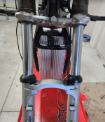

So, the project moves forward. I also have the BCM computer assembled and I've started writing firmware for it... More on that soon.
I'm starting with printed spacer plates, each holding one of the P groups (20 cells in my battery)

These have glue applied

The glue I'm using is a panel bonding polyurethane with a 50 shore hardness and 3MPa tensile strength.

Sikaflex make some stronger and stiffer polyurethanes, but this stuff is available at the local hardware store and will definitely be good enough.
The cells get a wipe down with alcohol and are then flame treated to improve adhesion.

The actual workflow is : Wipe cells, glue spacers, flame treat. This allows all the alcohol to flash off before I introduce fire to the picture.
Then they get stacked into the spacers with glue applied between each cell.


What works well here is that it's quite hard to make a mistake. All the cells in a P group go in the same way and the spacer plates determine where each cell should be.. It worked really well.
After a couple of days, each block is wrapped in tape to give just a little more insulation between groups.

I've now got both slices of the battery to this point. Next up is to glue the groups together, fit the temp sensors and spot weld the bus bars on.
Each of those groups feels really solid, I'd struggle to tear one apart. I think that bodes well for a good battery.. Pressing on, it's a big job!
In other news, a few adjustments were made and the battery box made it into the frame:

All those cardboard cutouts paid off with the thing being a perfect fit.


So, the project moves forward. I also have the BCM computer assembled and I've started writing firmware for it... More on that soon.
Last edited:
j bjork
1 MW
Cool, interesting to see how it moves along. What are your plans for bms?
I have an Ant BMS that'll handle 32S. I won't use the FET's on it to switch power though as it's only rated to 300A. Instead the BCM will talk to it and manage the charger, drive, display, and main contactor as needed.Cool, interesting to see how it moves along. What are your plans for bms?
There's a bit of bad press about BMS' failing. I suspect that it's mostly due to over current or under spec, so I should be OK with that. Nonetheless, The BMS will be external. You can't see it in those pics, but there's a 35pin circular connector on the top of the battery box for balance wires and thermistors.

Not wanting to further hijack Buildsix's thread KZ440 road legal cafe racer any more than I have already: The Vicor module I ordered arrived today.


Some good news, I cut the last panels for the battery box today:


I needed to see how the whole thing sat in the bike before deciding which of the rear panels was going to have the power terminals on it.
That panel and the lowest (ie furthest from my testicles) are cut from canvas phenolic sheet. The latter because it is where the 1000A fuse mounts.
I'll rub 'em back a bit and clearcoat with some 2 pack polyurethane at some point.
In other news, I'm grinding through the battery build..... I get that it's eating elephants, and I'm actually not bad at those kinds of tasks. But this is one seriously chubby elephant!
I've settled on this, only slightly sketchy, setup:

That PSU is good for 40A and, hidden behind that old car battery is this:

3S of 4500mAh LiPO goodness.
It's a bit of a lashup, but the K Weld will deliver 45J at one shot every 5 seconds (on average). I generally do about 30 welds then leave it for a bit because the 10mm solid copper electrodes get too hot to hold....
Come on hobbitses, long ways to go yet!


I needed to see how the whole thing sat in the bike before deciding which of the rear panels was going to have the power terminals on it.
That panel and the lowest (ie furthest from my testicles) are cut from canvas phenolic sheet. The latter because it is where the 1000A fuse mounts.
I'll rub 'em back a bit and clearcoat with some 2 pack polyurethane at some point.
In other news, I'm grinding through the battery build..... I get that it's eating elephants, and I'm actually not bad at those kinds of tasks. But this is one seriously chubby elephant!
I've settled on this, only slightly sketchy, setup:

That PSU is good for 40A and, hidden behind that old car battery is this:

3S of 4500mAh LiPO goodness.
It's a bit of a lashup, but the K Weld will deliver 45J at one shot every 5 seconds (on average). I generally do about 30 welds then leave it for a bit because the 10mm solid copper electrodes get too hot to hold....
Come on hobbitses, long ways to go yet!
- Joined
- Aug 8, 2022
- Messages
- 1,210
Still less sketchy than what I usedI've settled on this, only slightly sketchy, setup:
j bjork
1 MW
Alright, interesting battery setup. Was one or the other not enough?
I am very interested in your welder settings as I cant really make any testwelds..
I am very interested in your welder settings as I cant really make any testwelds..
"Interesting" is one way to put it... Yes, each battery on it's own ran out of go at 20-25J, I'm running 45J.Alright, interesting battery setup. Was one or the other not enough?
I am very interested in your welder settings as I cant really make any testwelds..
So the house move took me out for about 2 weeks! 
Today, I finally got to put a whole day into the project. It felt pretty damn good.
I've now got the battery assembled and spot welded. The 3D printed end plates for each P group and Sikaflex glue assembly, is VERY labour intensive, but produced a great result. The joints are solid without being brittle. I've no concerns about strain on the spot welds.
Building each P group as a sub assembly was good and bad. It was good because it's almost impossible to get it wrong and make smoke. It's bad because it's hard to not end up with gaps as you assemble the P groups into a battery. You can see some of those gaps in the previous post.
If you're doing it this way, make a template of the whole battery and use lots of clamps to make sure you don't end up with tolerance stackups.
I allowed 5mm extra space in the box for this. In one spot I needed 4mm!
Still, 4 is less than 5, so all is good
Today I put some self adhesive "battery paper" on the middle sides of the slices.
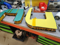
There's also a layer of 0.5mm fibreglass sheet between them.
Then I used hotmelt to tack the fuse and terminal mount bus plates on and, very carefully, loaded the first slice into the case.
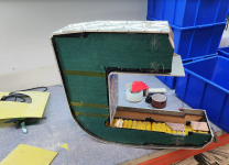
The MDF sheet is just there to insulate and give me a 6mm spacer. I'll replace it with some PU foam for final assembly.
The slice went in and out of the case a couple of times as I removed material from the end plates to get it to fit (see above for description).
Rinse and repeat for the other side and we get to the actual purpose of this assembly.
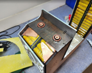

The output and fuse terminals (the fuse connects the two slices together and is thus in the middle of the stack) exit the battery through these phenolic plates. I wanted to hard solder the copper bosses to the bus-plates, but I obviously couldn't do that whilst they were spot welded to the cells. This assembly let me get their positions approximately marked on the bus plates.
Next step was to solder them on.
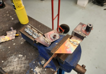
This went fairly well. I also added some extra copper to increase the mm^2 at the thin end of the battery.
They look a little rough after all the heat, but a quick sandblast cleaned them up nicely.
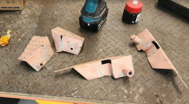
And now I could finally finish the (nearly) last of 3500 spot welds!
You get an idea of how each slice ended up in this pic.

Building the battery in two slices, connected by the fuse makes handling it heaps easier. Each slice weighs 21Kg. You can just about pick that up and put it in a metal box without anything going wrong (so long as you flip your access card lanyard to your back so that the metal ring on it doesn't short two groups, make a big spark, and scare the crap out of you).
The more astute of you will notice that I haven't added the BMS wiring yet. I'm just waiting on connectors...
Anyhow, it feels good to be making progress.
Today, I finally got to put a whole day into the project. It felt pretty damn good.
I've now got the battery assembled and spot welded. The 3D printed end plates for each P group and Sikaflex glue assembly, is VERY labour intensive, but produced a great result. The joints are solid without being brittle. I've no concerns about strain on the spot welds.
Building each P group as a sub assembly was good and bad. It was good because it's almost impossible to get it wrong and make smoke. It's bad because it's hard to not end up with gaps as you assemble the P groups into a battery. You can see some of those gaps in the previous post.
If you're doing it this way, make a template of the whole battery and use lots of clamps to make sure you don't end up with tolerance stackups.
I allowed 5mm extra space in the box for this. In one spot I needed 4mm!
Still, 4 is less than 5, so all is good
Today I put some self adhesive "battery paper" on the middle sides of the slices.

There's also a layer of 0.5mm fibreglass sheet between them.
Then I used hotmelt to tack the fuse and terminal mount bus plates on and, very carefully, loaded the first slice into the case.

The MDF sheet is just there to insulate and give me a 6mm spacer. I'll replace it with some PU foam for final assembly.
The slice went in and out of the case a couple of times as I removed material from the end plates to get it to fit (see above for description).
Rinse and repeat for the other side and we get to the actual purpose of this assembly.


The output and fuse terminals (the fuse connects the two slices together and is thus in the middle of the stack) exit the battery through these phenolic plates. I wanted to hard solder the copper bosses to the bus-plates, but I obviously couldn't do that whilst they were spot welded to the cells. This assembly let me get their positions approximately marked on the bus plates.
Next step was to solder them on.

This went fairly well. I also added some extra copper to increase the mm^2 at the thin end of the battery.
They look a little rough after all the heat, but a quick sandblast cleaned them up nicely.

And now I could finally finish the (nearly) last of 3500 spot welds!
You get an idea of how each slice ended up in this pic.

Building the battery in two slices, connected by the fuse makes handling it heaps easier. Each slice weighs 21Kg. You can just about pick that up and put it in a metal box without anything going wrong (so long as you flip your access card lanyard to your back so that the metal ring on it doesn't short two groups, make a big spark, and scare the crap out of you).
The more astute of you will notice that I haven't added the BMS wiring yet. I'm just waiting on connectors...
Anyhow, it feels good to be making progress.
stan.distortion
1 kW
- Joined
- Jun 12, 2019
- Messages
- 426
Really sorry I hadn't seen this thread earlier! Below is a project I'd started around 3 years ago and still haven't got around to building the battery for. The motor is a QS138 70H, not sure if there would be space for a 180 in the same location as there's not a whole lot of room between it and the lower frame tubes. It's been run with lipos and goes well, nothing earth shattering but quicker than the original 1000cc up to about 40mph and maxes out at about 70mph, easy 60mph cruising and down to about 50mph on steep hills. Belt drive works very well, tensioner is on the loaded side so not ideal but it's held solid. Nothing like as well engineered as your, really nice work!
Attachments
Ah, so you dropped the motor down below the frame rails! That's a really good idea.
I'm not going to figure out if I could have done that with the 180, because I might end up feeling stupid...
Nothing wrong with a belt drive, it's probably quieter than my gears. Given the lower current requirements of the 138, perhaps look at some LiFe cells? You can get some large capacity prismatic cells and only have to bolt 20 of them together. It's MUCH simpler than the approach I took.
stan.distortion
1 kW
- Joined
- Jun 12, 2019
- Messages
- 426
I've had LFO's sat here the whole time, just haven't got around to assembling them yet. The plan was pressure contact rather than welding as the cells put out 30a and that's a bit above the efficient limit for single strips of nickel, have the dies made up for stamping copper plate but not totally happy with my nickel plating procedure for the plates and not totally happy with the 3d printed frame I'd planned out holding them and clamping tight. Came across a load of 15mm acetal sheet recently though so it'll probably be revived using that soon...ish.
There's not a whole lot of capacity in those LFOs, enough for my day to day needs and they're both high output and long life so sacrificing watts/liter was a happy compromise. If more range is needed the plan is to hang additional li-ion packs off either side of the main pack, might look ok in a similar way to the BMW cylinders or it might look like something Volvo would've come out with in the 80's :/ Add pannier packs too and 100+ mile range should be possible while still having something light and nippy day to day (lightish anyway, they handle pretty well imho but they're no TZR!).
Good call on the forks, should look damn nice I'd totally forgotten how crappy BMW's standard disks are, that one was twin disk but I was short a hose so only put on one... an oil tanker would have better stopping distance! No idea what BMW were thinking when they "upgraded" to those things, the earlier drum brakes are good even by modern standards, plenty of power and really good feel and progression.
Really looking forward to how it works out, the QS180 wasn't out when I started that one and it's obviously a way better choice, should make for a lively bike!
There's not a whole lot of capacity in those LFOs, enough for my day to day needs and they're both high output and long life so sacrificing watts/liter was a happy compromise. If more range is needed the plan is to hang additional li-ion packs off either side of the main pack, might look ok in a similar way to the BMW cylinders or it might look like something Volvo would've come out with in the 80's :/ Add pannier packs too and 100+ mile range should be possible while still having something light and nippy day to day (lightish anyway, they handle pretty well imho but they're no TZR!).
Good call on the forks, should look damn nice
Really looking forward to how it works out, the QS180 wasn't out when I started that one and it's obviously a way better choice, should make for a lively bike!
I'm waiting on some connectors to finish the BMS wiring and using the time to finish off some mechanical tasks on the battery case.
I designed a bracket to tie the case to the top tube.

I did a test print and it fitted pretty well.
About 3 hours later, having started to make it from metal I found myself realising that, just because CAD makes it easy to produce complex shapes, doesn't mean it's a good idea to do so! Several setups and a lot of tiny cuts later:
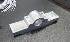

I designed a bracket to tie the case to the top tube.

I did a test print and it fitted pretty well.
About 3 hours later, having started to make it from metal I found myself realising that, just because CAD makes it easy to produce complex shapes, doesn't mean it's a good idea to do so! Several setups and a lot of tiny cuts later:


A big chunk of the weekend was spent doing the preliminary finishing on the battery box.
I started out sand blasting. This got most of the tooling marks

Then worked the tops o the ridges with an 80grit (pneumatic random orbit), followed by block sanding up to 600 grit and finishing with tripoli compound on a sisal wheel.


It's hard to see the look in this pic, they still need degreasing. I reckon it'll come out OK. Maybe a few tool marks visible, but good enough for the girls I go out with.
Time to set up the anodising tanks.
I started out sand blasting. This got most of the tooling marks

Then worked the tops o the ridges with an 80grit (pneumatic random orbit), followed by block sanding up to 600 grit and finishing with tripoli compound on a sisal wheel.


It's hard to see the look in this pic, they still need degreasing. I reckon it'll come out OK. Maybe a few tool marks visible, but good enough for the girls I go out with.
Time to set up the anodising tanks.
Wow, it's been a while. I've had some travel commitments at work that (along with the stack of stuff on my desk when I get back) have meant the bike project got sidelined. Sadly the rest of the year is looking even worse with some big trips coming up.
I'm determined to make progress when I can though, so this weekend I finished wiring all the BMS connectors:

The pack is 28s so there was lots of crimping and soldering, and more stupid screw ups than I'll ever admit to anyone!
Nonetheless, it lives:

I'm slow charging over the next day or so

I'll then top balance and do a deep discharge. The idea is that if there are any disconnected cells then it will show as a low voltage group.
It's not a perfect test, there could be a cell with only one spot weld that goes high resistance under load. But it's the best test I can think of..
I didn't get any pictures, but both slices got a run on a shaker table to help break anything loose that might be sketchy.
I'm determined to make progress when I can though, so this weekend I finished wiring all the BMS connectors:

The pack is 28s so there was lots of crimping and soldering, and more stupid screw ups than I'll ever admit to anyone!
Nonetheless, it lives:

I'm slow charging over the next day or so

I'll then top balance and do a deep discharge. The idea is that if there are any disconnected cells then it will show as a low voltage group.
It's not a perfect test, there could be a cell with only one spot weld that goes high resistance under load. But it's the best test I can think of..
I didn't get any pictures, but both slices got a run on a shaker table to help break anything loose that might be sketchy.
Similar threads
- Replies
- 83
- Views
- 3,760
- Replies
- 15
- Views
- 687
- Replies
- 5
- Views
- 1,056
- Replies
- 2
- Views
- 2,553


