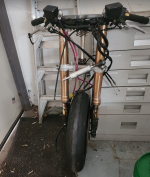
Street legal Cafe Racer build.

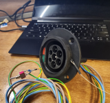
Another thing I've been doing is figuring out how to make this interface work to provide 240VAC to the onboard charger.
Screenshot 2024-06-04 175305.png
It turns out that, if you want less than 3KW then it's trivial to get the L2 charger to turn on. Just one resistor and 1 diode between the CP pin and earth. The mechanics of the plug ensure that you can never make or break an AC contact with current flowing.

So far I've tested against a generic Amazon 15A charger (230VAC nominal supply voltage in Australia) and a Tesla Wall Connector. Both work.
 
Last edited:
One of the things that I need to show is that the CG hasn't moved too much
Really?
I haven't seen any country imposing such requirement, that's very strange. Out of curiosity, where did you see that?

I'm not even sure how they can actually measure it, since CG on a bike varies a lot depending on the riders weight, position and the quantity of fuel or suspension setup.
 
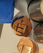
It feels like I'm forever waiting on parts with this project. Looks like the battery bus bars are at least a week away. But I should get the milling cutter I need to finish the battery box panels this week. So I've been working on those parts.
View attachment 354032View attachment 354033
There are many more .....

I like how your battery box design is coming out. Really nice design!
 
I like how your battery box design is coming out. Really nice design!
Thanks. I'm a bit bummed out that I can't do more to reflect the original lines of the bike in the actual hardware of the conversions. At some point I'll add some small fairings and covers and that will hopefully let me make it look a bit more like the flat twin it used to be.
 
Thanks. I'm a bit bummed out that I can't do more to reflect the original lines of the bike in the actual hardware of the conversions. At some point I'll add some small fairings and covers and that will hopefully let me make it look a bit more like the flat twin it used to be.
That was going to be my approach too. Rather than just leave a non descript box, design some sides that have a similar style to the original aluminium covers. Also using big sections of shaped heatsink to make the housing for the motor controller and contactors above the box to kind of emulate an air cooled motor. Making these types of conversions blend in to an older bike seems to be pretty challenging.
 
I gave up on all that and just leaned into the look of a totally new electric motorbike. Certainly is a lot easier to design for that!
 
I suspect there's more wisdom in your approach than mine! I may yet end up doing the same.
Laziness, or lack of design skill.

At one point, I looked at the fat orange cable coming out of the QS273 hub motor, and I scored some salvage automotive EV cable from a scrapyard that was also bright orange. So that's when I decided my build was going to be orange!
 
I think I said it took 4 goes to get the drive mounting bracket right.... I lied. 5th time's a charm!
Screenshot 2024-06-09 184301.png
Rotating the drive forward made for much better clearances.


Most of the weekend was spent working on some of the plates for the battery box.
Screenshot 2024-06-09 184600.png
Screenshot 2024-06-09 184855.png
1717930018808.png


There are a few more to make, some from that Tufnol sheet you see, and I may end up remaking some of them when I realise that I got the bend radius calculations wrong!

Overall though, I'm pretty happy with the progress.
 
So these got here today
Screenshot 2024-06-11 151805.png
Along with the PCB's for the body control module (BCM) and Type 2 charge interface controller.. I now have everything I need to finish the battery... I think...
 
Looks really nice! Are you planning on keeping all that visible still, I think it would look good in the final build
 
It turns out that, if you want less than 3KW then it's trivial to get the L2 charger to turn on. Just one resistor and 1 diode between the CP pin and earth.
The J1772 connector is the exact same way. Level2 charging stations are just gigantically large 240 switches, with the plug connection changing the resistance one a wire loop letting it know to ca-chunk down a big'ol contactor and let the juice flow.

DC charging ("level 3") is more complicated with an actual signaling protocol over some of the pins to negotiate DC voltage, amps, etc.
 
Incremental progress.
I've done nearly all the fit-up on the battery box. Just the two phenolic panels to make, but I need to get it in the bike for a dry fit to work out where the battery and fuse terminals need to be.
Screenshot 2024-06-18 071632.png

The first of the cell mount frames is complete
Screenshot 2024-06-18 071751.png
Screenshot 2024-06-18 071801.png

It turned out OK, not fantastic, but good enough.
 
Got a couple of these done today:

Screenshot 2024-06-21 092650.png

The design rules require a separate low voltage supply capable of running brake and hazard lights for half an hour or so.
This is overkill, but it switches on with the same active low signal that enables the VICOR DC/DC converters that buildsix KZ440 road legal cafe racer got a few of us excited about. It also has little balancing BMS built in..
 
Got a couple of these done today:

View attachment 355123

The design rules require a separate low voltage supply capable of running brake and hazard lights for half an hour or so.
This is overkill, but it switches on with the same active low signal that enables the VICOR DC/DC converters that buildsix KZ440 road legal cafe racer got a few of us excited about. It also has little balancing BMS built in..
very nice, do you have a link for it ,price etc thanks
 
very nice, do you have a link for it ,price etc thanks
Sorry, it's not a product, It's something I built. It's just 3 Cells, each with a HY2213 balancer IC and then a Relay (powered from the cells) with a transistor to turn it on (and a flyback diode)
 
Sorry, it's not a product, It's something I built. It's just 3 Cells, each with a HY2213 balancer IC and then a Relay (powered from the cells) with a transistor to turn it on (and a flyback diode)
how about a circuit for turning on off Vicor?
 
how about a circuit for turning on off Vicor?
Just pull the enable pin to ground. I'm wiring the key and handlebar on off switch in series and using them to bring up both the vicor module and the LV pack. This provides power to the body control module (more on that soon) which waits for the start button before pulling in the main contactor. The main contactor has the kill switch in series with it.
This meets the requirement for the contactor to drop if the key is turned off and keeps the lights on if I drop the contactor with the kill switch.

Public charging adds extra complexity. I want the BCM to come up to monitor charging and display the state of charge on the display when it's plugged in. But I don't want to have to leave my keys in the bike when I walk away.
So I'm going to use the PP line on the type 2 connector to also pull the enable low on the 12V supplies and use an output from the charge connector board I'm working on to tell the BCM that we're charging and that it should ignore the start button.
 
I tried......I failed!!!
I got this far into the battery assembly:
Screenshot 2024-06-23 181402.png
And realised that the PVC foam board just wasn't strong enough. It was starting to crack and distort as I added cells
Screenshot 2024-06-23 181417.png
I also had had some trouble holding Z tolerances when I machined it, so the 1mm web that was supposed to hold the cell axially, was missing on some holes.
Look, I could have easily got all the cells in the first side. But I'd have had *ZERO* chance of getting the other sheet pressed down onto it!

Talking with Doug, who's idea I had copied, and he confessed he'd had the same problem... THANKS DOUG! :mad:


So plan B is to print some, fairly minimal, end supports for each 'P' group of 20 cells (reminder, my pack is 28S20P) then assemble the P groups with the busbars and some glue.
Screenshot 2024-06-23 181456.pngScreenshot 2024-06-23 181514.png

The printer is working hard, and this approach lets me do things like put a couple of wraps of kapton tape around each P group, which is nice. But I fear that I may have over reacted and reduced the support for each cell too much. What I think I'm going to do is use some adhesive in the build process. I'm thinking some Sikaflex polyurethane, but I'm open to suggestions?
 
Back
Top