j bjork
1 MW
Cool, is pin 12 a ground pin on yours? Does it say version somewhere? The new v4 of the smaller controllers have some sort of 3speed switch input on pin 12.
Very expensive, heavy, and large teeth....Drives in this spec range are like hens teeth!
Is there a keyway between the output and coupling or just the M12 and taper fit holding the torque?It feels good to have the time to work on the bike again.
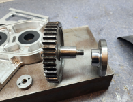
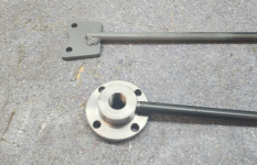
This morning I made these bits:
View attachment 351408
I turned an M12 (should have been a 14 or 16) x 1.25 thread on the end of the output shaft and ground a 4 degree taper on the end.
The output flange does double duty as the oil seal face, so it took some work holding trickery to maintain it's surface finish. It has a matching taper on the ID. Finally there's a nut to hold them together.
The output flange bolts up to a flange on the drive shaft.
View attachment 351409
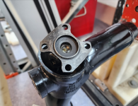
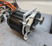
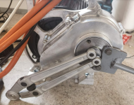
Made a few spacers from some stainless stock and got the front case mounted to the motor
View attachment 351410
No keyway, just a tapered interference fit of the output coupling on the 25mm shaft.Is there a keyway between the output and coupling or just the M12 and taper fit holding the torque?
Ok, I'm no mechanical engineer but have always noticed a keyway or splines when working on cars for power/torque transfer couplings. Based on the quality of your previous work in this build I'm sure you've done the calcs and it's all good.No keyway, just a tapered interference fit of the output coupling on the 25mm shaft.
Taper fits are a little hard to calculate, but a shrink fit of 0.025mm (1 thou) in a 25mm shaft with 20mm of engagement is good for 200Nm of torque.Ok, I'm no mechanical engineer but have always noticed a keyway or splines when working on cars for power/torque transfer couplings. Based on the quality of your previous work in this build I'm sure you've done the calcs and it's all good
Apologies, it took a while to get to wiring the control. The manual lists pin 12 as GND.Cool, is pin 12 a ground pin on yours? Does it say version somewhere? The new v4 of the smaller controllers have some sort of 3speed switch input on pin 12.
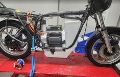
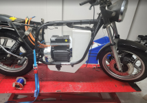
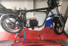
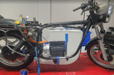
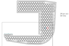
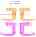
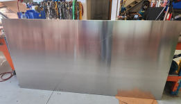
This drawing and your previous sketch seems to show that your cells are physically touching each other. What's your plan for cell holders, if any? Myself and others will suggest that in a mobile application, the cells could vibrate against each other and short. If you do still want to go that route, you may want to double or triple shrink-wrap your cells.So this week I got stuck into the battery. I did one more cardboard mockup, just to tweak some mounting points and that got me my final battery layout which that let me order the busbars.
View attachment 353135
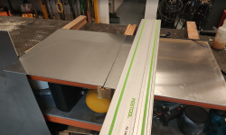
Then I started on the box:
View attachment 353136
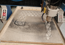
View attachment 353137
View attachment 353138
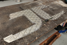
The side plates are done, and I'm pretty happy with how they've turned out.
View attachment 353139
LOTS more CAD and swarf to go, but any day you cut metal is a good day.....
The cells have about 0.5mm clearance and are held by a plate on each end machined from PVC foam, a bit like thisThis drawing and your previous sketch seems to show that your cells are physically touching each other. What's your plan for cell holders, if any? Myself and others will suggest that in a mobile application, the cells could vibrate against each other and short. If you do still want to go that route, you may want to double or triple shrink-wrap your cells.
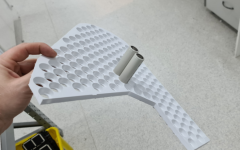
Excellent, looks greatThe cells have about 0.5mm clearance and are held by a plate on each end machined from PVC foam, a bit like this
View attachment 353150
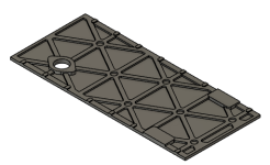
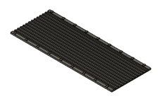
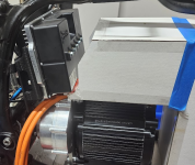
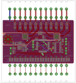
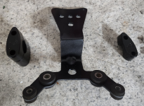
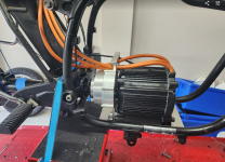
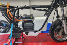
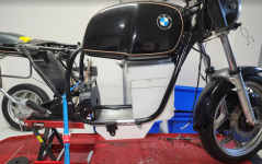
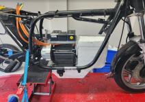
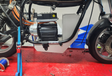
The controller is quite heavy at 4Kg, I'm trying to A, keep the weight as low as I can in the bike, and B keep the cable runs short.Wasn't it possible to fit the controller under the gas tank, on the frame bars?
That would make maintenance a fair bit easier, plus more freedom in case you want to test other controllers later. It would also get much better airflow for cooling.
You could fit the charger here instead.
The heatsink of the controller is connected to GND? that's weird, is there some kind of insulation defect or do these controllers come wired this way? First time I hear that.
Having the load as low as possible isn't necessarily a good thing on a bike, unlike a car.The controller is quite heavy at 4Kg, I'm trying to A, keep the weight as low as I can in the bike, and B keep the cable runs short.
The charger is quite light (around 1Kg IIRC) so it goes up top. Re airflow. The controller is in the part of the frame where I can duct quite a lot of air if I need to..
Sure, but recall that I'm not trying to build the perfect bike, I'm trying to build a bike that will be signed off on by a government official. One of the things that I need to show is that the CG hasn't moved too much. A BMW R80 has a very low CG, we measured it before I started this project.Having the load as low as possible isn't necessarily a good thing on a bike, unlike a car.
The center of gravity must be on a line going from the pivot point of the steering to the rear tire (or something like that, I'm not an expert but I did read a book on motorcycle geometry after I crashed my bike lol).
A good rule of thumb is that the CG should be at a height around half of the motorcycle wheelbase.
As for the cable lenghts, it will not matter, the difference is negligible.
But I do understand these points, as I did the very same mistake a few years ago for the very same reasons
